Pavement Marking Design Manual: Difference between revisions
Bruce Wacker (talk | contribs) |
Brian Geiger (talk | contribs) m →High-Visibility Crosswalk Markings: Added paragraphs. |
||
| (240 intermediate revisions by 4 users not shown) | |||
| Line 1: | Line 1: | ||
== General Purpose of the Design Manual == | == General Purpose of the Design Manual == | ||
'''<font color="red">Last Revised | '''<font color="red">Last Revised July 2024</font>'''<br>Pavement Marking Design Manual has been written to serve as a general guideline when designing pavement markings for the City of Overland Park, Kansas. Although there are specific design requirements, the guidelines contained herein should not be a substitute for proper engineering design and judgment based on specific situations. All pavement markings shall comply with the latest adopted edition of the Manual on Uniform Traffic Control Devices (MUTCD). The purpose of this Pavement Marking Design Manual is to aid consultants as well as City of Overland Park staff to be consistent in the practice of designing pavement marking plans. It provides an overview of what tasks are expected to be included in the scope of the design; what information should be included on the plan sheets; what kind of backup design information is required; and what is expected for the final deliverable product. Any questions regarding this manual may be directed to Brian Geiger, Supervisory Traffic Engineer Engineer at the City of Overland Park, Kansas at (913) 895-6020 or by email at <font color="blue">Brian.Geiger@opkansas.org.</font> | ||
=== Purpose of Pavement Marking: === | === Purpose of Pavement Marking: === | ||
Pavement marking provides guidance and information to the roadway user as well as supplement other traffic control devices such as signs, traffic signals and other markings. Pavement markings can convey regulations, guidance, or warnings. | Pavement marking provides guidance and information to the roadway user as well as supplement other traffic control devices such as signs, traffic signals and other markings. Pavement markings can convey regulations, guidance, or warnings. | ||
Wherever applicable, this design manual should be used in conjunction with the latest adopted edition of the [https://mutcd.fhwa.dot.gov/ | Wherever applicable, this design manual should be used in conjunction with the latest adopted edition of the [https://mutcd.fhwa.dot.gov/kno_11th_Edition.htm<u><font color="blue">Manual on Uniform Traffic Control Devices (MUTCD)</font>]</u> by the Federal Highway Administration. The current editions of the [https://www.opkansas.org/city-services/building-construction/civil-engineering/construction-standards/ <font color="blue">Design and Construction Standards, Volume 2 Construction Specifications (latest edition)</font>], the latest edition of the [https://drive.google.com/file/d/1bIGwfekpRZm8O7R4sHaKTiqxFKb9Wlev/view <font color="blue">Pavement Marking Standard Details</font>] and the [https://ppm.opkansas.org/wiki/index.php/Approved_Materials <font color="blue">Approved Materials List</font>], hereafter referred to as “City Standards” should be followed during the design of all pavement marking plans. | ||
== Public or Private Ownership and Maintenance == | == Public or Private Ownership and Maintenance == | ||
| Line 20: | Line 19: | ||
== Functional Roadway Classifications == | == Functional Roadway Classifications == | ||
The following pavement marking design criteria will be used for all thoroughfare roadways, super collector roadways, collector roadways and residential roadways as identified on the latest edition of the City of Overland Park [ | The following pavement marking design criteria will be used for all thoroughfare roadways, super collector roadways, collector roadways and residential roadways as identified on the latest edition of the City of Overland Park [https://drive.google.com/file/d/1VcyyryorZldaO5RUxDfgfW1GhqFVs2Rg/view <font color=blue>“Official Street Map”</font>] available from the Planning and Development Services Department. | ||
=== Thoroughfare Roadway === | === Thoroughfare Roadway === | ||
| Line 106: | Line 105: | ||
Yellow centerline markings are used to delineate the separation of traffic lanes that have opposite directions of travel. They are used on thoroughfare roadways, collector roadways, and super collector roadways regardless of the posted speed. Centerline markings are not installed on residential roadways except in specific situations in advance of intersections as addressed below. | Yellow centerline markings are used to delineate the separation of traffic lanes that have opposite directions of travel. They are used on thoroughfare roadways, collector roadways, and super collector roadways regardless of the posted speed. Centerline markings are not installed on residential roadways except in specific situations in advance of intersections as addressed below. | ||
The yellow centerline markings, whether broken or solid double lines, should be continuous through residential drive entrances and alleys but should break at intersections with public streets and private streets as defined above. Breaks in the centerline should not be made at single family or multi-family drive entrances. They should also not be broken at intersections with commercial drive entrances unless the main roadway has left or right turn lanes accessing the site or the intersection with the commercial drive is controlled by a traffic signal. | The yellow centerline markings, whether broken or solid double lines, should be continuous through residential drive entrances and alleys but should break at intersections with public streets and private streets as defined above. Breaks in the centerline should not be made at single family or multi-family drive entrances. They should also not be broken at intersections with commercial drive entrances unless the main roadway has left or right turn lanes accessing the site or the intersection with the commercial drive is controlled by a traffic signal. Where a horseshoe cds intersects and creates a T-intersection, break the yellow centerline markings at the tangent points and place a dash at the median. If the horseshoe cds is a 4-way intersection, break the yellow centerline markings at the tangent points and do not place a dash at the median. | ||
At breaks in the centerline, the beginning and end of the centerline should be evaluated based on the left turn movement of the design vehicle from the side street. The beginning or end of the line should be at the point where the design vehicle does not drive over the line while making a left turn. This should be determined using turning movement templates for the specific design vehicle. | At breaks in the centerline, the beginning and end of the centerline should be evaluated based on the left turn movement of the design vehicle from the side street. The beginning or end of the line should be at the point where the design vehicle does not drive over the line while making a left turn. This should be determined using turning movement templates for the specific design vehicle. | ||
=== Centerlines on Residential Streets === | === Centerlines on Residential Streets === | ||
Centerlines are not typically installed on residential streets. However, the following | Centerlines are not typically installed on residential streets. However, the following condition would warrant centerline markings near intersections with other streets: | ||
# When a residential street has more than one approach lane to an intersection that is marked with solid white lane markings, a double yellow centerline should be installed in advance of the stop line for a minimum of 50’ or for the length of the solid white lane markings. | # When a residential street has more than one approach lane to an intersection that is marked with solid white lane markings, a double yellow centerline should be installed in advance of the stop line for a minimum of 50’ or for the length of the solid white lane markings. | ||
=== Centerlines on Collector Streets === | === Centerlines on Collector Streets === | ||
All two-lane collector streets, regardless of width, shall be striped with a centerline consisting of a 4” wide broken yellow line with a 6’ stripe and an 18’ gap (3:1 ratio). Collector streets that consist of more than two lanes shall be striped with a 4" solid double yellow centerline. | All two-lane collector streets, regardless of width, shall be striped with a centerline consisting of a 4” wide broken yellow line with a 6’ stripe and an 18’ gap (3:1 ratio). Collector streets that consist of more than two lanes shall be striped with a 4" solid double yellow centerline. | ||
See the section on [[#Transitions from | See the section on [[#Transitions from Normal Centerlines|<font color = "blue">Transitions from Normal Centerlines</font Color>]] below for treatment of centerlines at intersections. | ||
=== Centerlines on Apartment Streets === | === Centerlines on Apartment Streets === | ||
Apartment streets that are 36’ wide (measured from back of curb to back of curb), that have a posted speed limit of 30 mph, shall have a marked centerline consisting of a 4” wide broken yellow line with a 6’ stripe and an 18’ gap (3:1 ratio). | Apartment streets that are 36’ wide (measured from back of curb to back of curb), that have a posted speed limit of 30 mph, shall have a marked centerline consisting of a 4” wide broken yellow line with a 6’ stripe and an 18’ gap (3:1 ratio). | ||
See the section on [[#Transitions from | See the section on [[#Transitions from Normal Centerlines|<font color = "blue">Transitions from Normal Centerlines</font Color>]] below for treatment of centerlines at intersections. | ||
=== Centerlines on Commercial and Industrial Streets === | === Centerlines on Commercial and Industrial Streets === | ||
Commercial streets or industrial streets may range in width from 36’ to 52’ (measured from back of curb to back of curb) to accommodate left or right turn lanes or additional through lanes for added vehicle capacity. Centerlines should consist of 4” wide broken yellow lines with a 6’ stripe and an 18’ gap (3:1 ratio) or 4” solid double yellow lines depending on the number of lanes. Broken yellow centerlines would be used where there are no auxiliary lanes such as right or left turn lanes. Double yellow centerlines should be used at multi-lane cross-sections and may terminate at an intersection with a painted median. Depending on the number of access points, a two-way left turn lane may be provided as approved by the City Engineer. [[#Painted Medians|<font color = "blue">Painted medians</font color>]] and [[#Two-way Left Turn Lanes (TWLTL)|<font color = "blue">Two-way left turn lanes</font color>]] are discussed below. | Commercial streets or industrial streets may range in width from 36’ to 52’ (measured from back of curb to back of curb) to accommodate left or right turn lanes or additional through lanes for added vehicle capacity. Centerlines should consist of 4” wide broken yellow lines with a 6’ stripe and an 18’ gap (3:1 ratio) or 4” solid double yellow lines depending on the number of lanes. Broken yellow centerlines would be used where there are no auxiliary lanes such as right or left turn lanes. Double yellow centerlines should be used at multi-lane cross-sections and may terminate at an intersection with a painted median. Depending on the number of access points, a two-way left turn lane may be provided as approved by the City Engineer. [[#Painted Medians|<font color = "blue">Painted medians</font color>]] and [[#Two-way Left Turn Lanes (TWLTL)|<font color = "blue">Two-way left turn lanes</font color>]] are discussed below. | ||
See the section on [[#Transitions from | See the section on [[#Transitions from Normal Centerlines|<font color = "blue">Transitions from Normal Centerlines</font Color>]] below for treatment of centerlines at intersections. | ||
=== Centerlines on Super-Collector Roadways === | === Centerlines on Super-Collector Roadways === | ||
Super-collector roadways range from two undivided through lanes that are 36’ wide (back of curb to back of curb), to divided roadways with four through lanes. Centerline pavement markings should either be 4” wide broken yellow line with a 6’ stripe and an 18’ gap (3:1 ratio) or 4” solid double yellow lines depending on the number of lanes. Broken yellow centerlines would be used on two-lane super-collector streets where there are no auxiliary lanes such as right or left turn lanes, while double yellow centerlines should be used at multi-lane cross-sections. Proper transitions between broken centerlines and painted or raised medians should be provided as discussed in [[#Transitions from | Super-collector roadways range from two undivided through lanes that are 36’ wide (back of curb to back of curb), to divided roadways with four through lanes. Centerline pavement markings should either be 4” wide broken yellow line with a 6’ stripe and an 18’ gap (3:1 ratio) or 4” solid double yellow lines depending on the number of lanes. Broken yellow centerlines would be used on two-lane super-collector streets where there are no auxiliary lanes such as right or left turn lanes, while double yellow centerlines should be used at multi-lane cross-sections. Proper transitions between broken centerlines and painted or raised medians should be provided as discussed in [[#Transitions from Normal Centerlines|<font color = "blue">Transitions from Normal Centerlines</font color>]] below. Depending on the number of access points, a two-way left turn lane may be provided as approved by the City Engineer. [[#Two-way Left Turn Lanes (TWLTL)|<font color = "blue">Two-way left turn lanes</font color>]] are discussed below. | ||
=== Centerlines on Thoroughfare Roadways === | === Centerlines on Thoroughfare Roadways === | ||
| Line 144: | Line 142: | ||
Divided thoroughfare roadways that have a continuous median, except for breaks at approved intersections, do not require centerline pavement markings if the center median consists of raised curbs. When the center median is depressed, the centerline pavement marking should consist of a single 4” solid yellow edge line on each side of the depressed median. The yellow edge line should be installed 4” from the edge of the driving surface to the closest edge of the line. | Divided thoroughfare roadways that have a continuous median, except for breaks at approved intersections, do not require centerline pavement markings if the center median consists of raised curbs. When the center median is depressed, the centerline pavement marking should consist of a single 4” solid yellow edge line on each side of the depressed median. The yellow edge line should be installed 4” from the edge of the driving surface to the closest edge of the line. | ||
Thoroughfares with intermittent raised medians shall have a 4” solid double yellow centerline in those sections that do not have a center median. Any time a raised median section is provided, centerline markings are not required. Proper transitions between broken centerlines and painted or raised medians should be provided as discussed in [[#Transitions from | Thoroughfares with intermittent raised medians shall have a 4” solid double yellow centerline in those sections that do not have a center median. Any time a raised median section is provided, centerline markings are not required. Proper transitions between broken centerlines and painted or raised medians should be provided as discussed in [[#Transitions from Normal Centerlines|<font color = "blue">Transitions from Normal Centerlines</font color>]] below. | ||
==== Centerlines on Undivided, Improved Thoroughfare Roadways ==== | ==== Centerlines on Undivided, Improved Thoroughfare Roadways ==== | ||
| Line 211: | Line 209: | ||
|- style="text-align: center" | |- style="text-align: center" | ||
|Special Situations at Intersections | |Special Situations at Intersections | ||
|} | |||
==== Special Situations at Midblock Crosswalks ==== | |||
At midblock crosswalks, across roadways with a marked centerline, the broken yellow centerline should transition to a double yellow centerline in advance of the midblock crosswalk for a distance of approximately 50'. A 3' minimum gap should be provided between the double yellow centerline and the marked crosswalk. | |||
<br> | |||
{| style="border-spacing: 2px; border: 1px solid black;" align="center" | |||
|- border="0" | |||
| [[File:Centerline Transition at midblock crosswalk.JPG|800px|]] | |||
|- style="text-align: center" | |||
|Special Situations at Midblock Crosswalks | |||
|} | |} | ||
| Line 217: | Line 225: | ||
Painted medians also occur in advance of a raised median that has been installed for access control near an intersection approach or in advance of a splitter island of a roundabout. | Painted medians also occur in advance of a raised median that has been installed for access control near an intersection approach or in advance of a splitter island of a roundabout. | ||
Painted medians should consist of 4” solid double yellow lines with 12” yellow diagonal crosshatch lines. See [[#Yellow Diagonal Crosshatch | Painted medians should consist of 4” solid double yellow lines with 12” yellow diagonal crosshatch lines. See [[#Yellow Diagonal Crosshatch Markings|<font color = "blue">Yellow Diagonal Crosshatch Lines</font color>]] for more information. | ||
=== Yellow Solid and Broken Lane Lines === | === Yellow Solid and Broken Lane Lines === | ||
| Line 226: | Line 234: | ||
Two-way left turn lanes (TWLTL) should consist of 4” solid yellow lines on each side of the travel lane with six foot long 4” broken yellow lines inset inside of the solid yellow lines with 18’ long gaps. The beginning and end of the broken yellow lines should line up with any adjacent broken white lane lines. | Two-way left turn lanes (TWLTL) should consist of 4” solid yellow lines on each side of the travel lane with six foot long 4” broken yellow lines inset inside of the solid yellow lines with 18’ long gaps. The beginning and end of the broken yellow lines should line up with any adjacent broken white lane lines. | ||
The TWLTL should terminate into a left turn lane. There should be a 42’ long gap between the end of the broken and solid yellow line and the beginning of the 4” solid white lane line for the left turn storage. | The TWLTL should terminate into a left turn lane. The TWLTL lane markings should not extend to intersections. There should be a 42’ long gap between the end of the broken and solid yellow line and the beginning of the 4” solid white lane line for the left turn storage. | ||
Two sets of white left turn arrows should be placed 25’ apart measured from the tails of both arrows. The spacing of the arrow sets is dependent on the overall length of the TWLTL. Generally, one set is installed 30’ from the beginning, one set 30’ from the end and one set at approximately the midpoint, but the distance between sets of arrows should not exceed 160’. | Two sets of white left turn arrows should be placed 25’ apart measured from the tails of both arrows. The spacing of the arrow sets is dependent on the overall length of the TWLTL. Generally, one set is installed 30’ from the beginning, one set 30’ from the end and one set at approximately the midpoint, but the distance between sets of arrows should not exceed 160’. | ||
| Line 268: | Line 276: | ||
|} | |} | ||
Broken white lane lines should break on each side of a four-legged intersection, comprised of public streets, allowing side street traffic to cross without running over the lines. Broken white lane lines should extend through intersections with private and commercial driveways. However, if the main street has a left turn lane into the commercial drive of the development, lane lines should not be marked through the intersection. It would be treated like a standard intersection with public streets. | Broken white lane lines should break on each side of a four-legged intersection, comprised of public or private streets, allowing side street traffic to cross without running over the lines. Broken white lane lines should extend through intersections with private and commercial driveways. However, if the main street has a left turn lane into the commercial drive of the development, lane lines should not be marked through the intersection. It would be treated like a standard intersection with public streets. | ||
{| style="border-spacing: 2px; border: 1px solid black;" align="center" | {| style="border-spacing: 2px; border: 1px solid black;" align="center" | ||
| Line 378: | Line 386: | ||
=== Wide Dotted Lane Drop Line === | === Wide Dotted Lane Drop Line === | ||
Wide dotted lane drop lines are used for lane drops (trap lanes) where an otherwise through traffic lane turns into a mandatory left turn or right turn lane. Where used, the wide dotted lane drop line shall be 8” wide with a 3’ line segment and a 9’ gap. The wide dotted lane drop line will be accompanied by a 8” wide white solid lane line beginning at the downstream end of the white dotted lane drop line to the stop bar (See [[#Solid | Wide dotted lane drop lines are used for lane drops (trap lanes) where an otherwise through traffic lane turns into a mandatory left turn or right turn lane. Where used, the wide dotted lane drop line shall be 8” wide with a 3’ line segment and a 9’ gap. The wide dotted lane drop line will be accompanied by a 8” wide white solid lane line beginning at the downstream end of the white dotted lane drop line to the stop bar (See [[#White Solid Wide Lane Lines|<font color = "blue">White Solid Wide Lane Lines</font color>]]). The length of the dotted lane drop shall be as follows: | ||
{| style="border-spacing: 2px; border: 1px solid black;" align="center" | {| style="border-spacing: 2px; border: 1px solid black;" align="center" | ||
|- border="0" | |- border="0" | ||
| Line 398: | Line 406: | ||
==== Spacing Considerations for Closely Spaced Intersections ==== | ==== Spacing Considerations for Closely Spaced Intersections ==== | ||
If the calculated length of the wide dotted lane drop line would extend it into or through an upstream four-legged intersection (whether controlled or uncontrolled), it should begin immediately past the upstream intersection instead of using the full calculated length. The lane drop line should begin no closer to the intersection than the most upstream regulatory or warning sign associated with the lane drop. An R3-7 (R or L) sign should be installed approximately 30’ from the curb return at the | If the calculated length of the wide dotted lane drop line would extend it into or through an upstream four-legged intersection (whether controlled or uncontrolled), it should begin immediately past the upstream intersection instead of using the full calculated length. The lane drop line should begin no closer to the intersection than the most upstream regulatory or warning sign associated with the lane drop. An R3-7 (R or L) sign should be installed approximately 30’ from the curb return at the intersection. An additional R3-7 (R or L) should be installed at the beginning of the 8" solid wide lane line. | ||
The calculated length of the wide dotted lane drop line can extend through a three-legged T-intersection as long as the major street that has the trap lane is divided with a median. In that case, an R3-7R sign will be installed at the beginning of the wide dotted lane drop line with a street name sign plaque mounted underneath to designate where the lane drops. | The calculated length of the wide dotted lane drop line can extend through a three-legged T-intersection as long as the major street that has the trap lane is divided with a median. In that case, an R3-7R sign will be installed at the beginning of the wide dotted lane drop line with a street name sign plaque mounted underneath to designate where the lane drops. | ||
| Line 429: | Line 437: | ||
|} | |} | ||
---- | ---- | ||
== Solid White Lane Lines == | == Solid White Lane Lines == | ||
Solid white lane lines are used where drivers are discouraged from changing lanes. The lane line markings shall consist of a 4” wide solid white line. Solid white lane lines are typically used at intersections to separate a through lane from a mandatory left or right turn lane. | Solid white lane lines are used where drivers are discouraged from changing lanes. The lane line markings shall consist of a 4” wide solid white line. Solid white lane lines are typically used at intersections to separate a through lane from a mandatory left or right turn lane. | ||
| Line 462: | Line 471: | ||
|Solid White Lane Line Exception for Continuous Right Turn Lanes | |Solid White Lane Line Exception for Continuous Right Turn Lanes | ||
|} | |} | ||
---- | |||
{| width="800px" border="0" cellpadding="4" cellspacing="0"; border-collapse: collapse;" | |||
|+ | |||
|align="left" width="30px"|[[File:Up arrow 66x80.png|50px|link=#top]] | |||
| align="left"|[[#top|'''Top''']] | |||
| align="right"|[[#Solid White Lane Lines|'''Solid White Lane Lines''']] | |||
| align="right" width="30px"|[[File:Side arrow 80x66.png|50px|right|link=Solid White Lane Lines]] | |||
|} | |||
---- | |||
== Solid Double White Lane Lines == | == Solid Double White Lane Lines == | ||
Solid double white lane lines are used to mark where crossing is prohibited or whenever two lanes of traffic, traveling in the same direction, are separated by a painted median. The most common instance of this occurs between a turn lane and a through lane which is separated by a painted island. This normally occurs when an intersection has offset left turn lanes that are separated from the through lanes to give drivers on opposing approaches a less obstructed view of opposing through traffic. They are also used when an intersection is designed for ultimate double left turn lanes, but one lane has been marked out until sometime in the future when it is required based on traffic volumes. The lane line markings shall consist of a 4” wide solid double white lines separated by a 4” space. White 12” chevron should be installed between the two sets of solid double white lane lines. See | Solid double white lane lines are used to mark where crossing is prohibited or whenever two lanes of traffic, traveling in the same direction, are separated by a painted median. The most common instance of this occurs between a turn lane and a through lane which is separated by a painted island. This normally occurs when an intersection has offset left turn lanes that are separated from the through lanes to give drivers on opposing approaches a less obstructed view of opposing through traffic. They are also used when an intersection is designed for ultimate double left turn lanes, but one lane has been marked out until sometime in the future when it is required based on traffic volumes. The lane line markings shall consist of a 4” wide solid double white lines separated by a 4” space. White 12” chevron should be installed between the two sets of solid double white lane lines. (See [[#White Chevron Markings|<font color = "blue">White Chevron Markings</font color>]]) for more information in regard to spacing. | ||
{| style="border-spacing: 2px; border: 1px solid black;" align="center" | |||
|- border="0" | |||
| [[File:Double White Lane Lines.JPG|800px|]] | |||
|- style="text-align: center" | |||
|Solid Double White Lane Lines | |||
|} | |||
== White Solid Wide Lane Lines == | |||
Solid wide channelization lines are used to form islands where traffic traveling in the same direction is permitted on both sides of the island. They should be 8” wide and used to outline around painted or raised medians as follows: | |||
=== At Interchange Ramps === | |||
Channelizing lines at entrance ramps define the neutral area, directing exiting traffic at the proper angle for smooth divergence onto the ramp. They should be used to outline raised islands or used for painted islands that separate interstate ramp movements from through movements on thoroughfare streets. | |||
{| style="border-spacing: 2px; border: 1px solid black;" align="center" | |||
|- border="0" | |||
| [[File:Solid Wide Lane Lines Around Island at Ramps.JPG|600px|]] | |||
|- style="text-align: center" | |||
|White Solid Wide Lane Lines at Interstate Ramp Islands | |||
|} | |||
=== At Free Flow Right Turn Lanes === | |||
They should also be used to outline the raised medians for free flow right turn lanes on City streets. | |||
{| style="border-spacing: 2px; border: 1px solid black;" align="center" | |||
|- border="0" | |||
| [[File:Solid Wide Lane Lines Around Islands at Intersections.JPG|600px|]] | |||
|- style="text-align: center" | |||
|White Solid Wide Lane Lines Around Islands at Intersections | |||
|} | |||
---- | |||
{| width="800px" border="0" cellpadding="4" cellspacing="0"; border-collapse: collapse;" | |||
|+ | |||
|align="left" width="30px"|[[File:Up arrow 66x80.png|50px|link=#top]] | |||
| align="left"|[[#top|'''Top''']] | |||
| align="right"|[[#White Solid Wide Lane Lines|'''White Solid Wide Lane Lines''']] | |||
| align="right" width="30px"|[[File:Side arrow 80x66.png|50px|right|link=White Solid Wide Lane Lines]] | |||
|} | |||
---- | |||
== White Edge Lines == | |||
Edge lines are 4” wide lines that are used to delineate the right or left edges of roadways that have paved or turf shoulders. If they are on the left hand side of the roadway, they shall be yellow. They shall be white if they are on the right hand side of the roadway. Edge lines shall not be continued through intersections or major driveways that consist of turn lanes entering from the major street. But they would extend through minor driveways. They should be placed on rural thoroughfares and collectors with a traveled way of 20’ or more and an average daily traffic (ADT) of 3,000 vehicles per day or greater. If a bicycle lanes is marked on the outside portion of the traveled way, the edge line that would mark the outside edge of the bicycle lane should be omitted. | |||
In the case of turf shoulders, the edge line shall be inset to allow a minimum of 4” from the edge of the asphalt roadway to the edge of the line. | |||
=== Edge Lines on Diverging Diamond Interchanges (DDI’s) === | |||
Edge lines on diverging diamond interchanges (DDI’s) require clarification. The two directions of travel are separated by either a raised median or bridge rails. This would normally require the edge line separating the two directions of travel to be yellow. However, this violates the rule that yellow lines shall always be on the left hand side of the driver. Therefore, the pavement for the two directions of travel are treated as separate, one-way roadways. Therefore, the edge lines will be yellow on the left side and white on the right side for drivers traveling in each direction. | |||
{| style="border-spacing: 2px; border: 1px solid black;" align="center" | |||
|- border="0" | |||
| [[File:Edge Lines for DDIs.jpg|800px|]] | |||
|- style="text-align: center" | |||
|Edge Lines for Diverging Diamond Interchanges (DDI's) | |||
|} | |||
=== Edge Lines on Bridges === | |||
Edge lines should be installed across all bridges, regardless of whether the roadway approaches to the bridge consist of curb and gutter or shoulders. The edge line should be offset from the bridge rail to provide a horizontal buffer space for vehicles and to maintain a constant lane width across the bridge. The solid white edge line across a bridge should be eliminated if a bicycle lane exists. The solid white line on the left side of the bicycle lane will act as the vehicle edge line. | |||
== White Stop Lines == | |||
Stop lines indicate the point behind which vehicles are required to stop in compliance with a STOP sign. Stop lines may be either 12” wide or 24” wide, and shall be based on the stop sign size as required by the Manual on Uniform Traffic Control Devices (MUTCD). If the STOP sign size should be 30”, the stop line should be 12” wide . If the STOP sign size should be 36” or larger, the stop line should be 24” wide. At all-way stop controlled intersections, the stop bars and stop signs shall be the same size on all approach legs and based on the largest sign size required at the intersection according to the MUTCD and Overland Park Stop Sign Guidelines [[Media:Stop sign size flow chart.pdf|<font color="blue">flowchart</font>]]. At signalized intersections, the stop line on all approaches should be 24” wide. The following are general guidelines for white stop lines. (Refer to [[#Crosswalk and Stop Line Usage|<font color = "blue">Crosswalk and Stop Line Usage</font color>]]) for specific guidance regarding when to install them. | |||
=== Stop Lines in Conjunction with Crosswalks === | |||
In general, a stop line should always be installed in advance of a crosswalk on an approach that is controlled by stop sign. | |||
=== Stop Lines for Standard Intersections Without Skew === | |||
In general, the stop lines should typically be perpendicular to the lane of travel and extend across all lanes as a continuous straight line. Stop lines shall be installed such that they are not located in the vehicle path of left turn movements from the side street approach. This is particularly critical where there is no median separating opposing through lanes. Where raised medians exist, the stop line for the left turn lane should generally be located at the median nose. | |||
The minimum separation from the trailing edge of the stop line to the leading edge of the crosswalk line shall be 4’. If the distance from the crosswalk line or theoretical crosswalk line is greater than 15', consider staggering the stop lines for the through lanes closer to the intersection, to minimize this distance. This occurs when the median nose is pulled back to accommodate left turning vehicles from the side street. Do not stagger the stop line if the distance between the staggered stop line for the left turn lanes and the through lanes would be less than 5’, even if the distance exceeds 15'. | |||
{| style="border-spacing: 2px; border: 1px solid black;" align="center" | |||
|- border="0" | |||
| [[File:Stop Lines at Intersections without Skew.jpg|800px|]] | |||
|- style="text-align: center" | |||
|Stop Lines at Intersections without Skew | |||
|} | |||
=== Stop Lines for Skewed Intersections === | |||
In the case of severely skewed intersections, several things should be taken into consideration. The stop line should generally be installed parallel to the crosswalk lines as long as the vehicle position for the farthest right hand lane is closer to the intersection than the left turn vehicle to avoid obscuring the intersection sight distance for right turn vehicles making right turns on red signal indications. Where raised medians exist, the stop line for the left turn lane should generally be located at the median nose. The minimum separation from the trailing edge of the stop line to the leading edge of the crosswalk line shall be 4’. If the distance from the crosswalk line or theoretical crosswalk line is greater than 15', consider staggering the stop lines for the through lanes closer to the intersection, to minimize this distance. This occurs when the median nose is pulled back to accommodate left turning vehicles from the side street. Do not stagger the stop line if the distance between the staggered stop line for the left turn lanes and the through lanes would be less than 5’, even if the distance exceeds 15'. On the other legs, install the stop lines perpendicular to the vehicle path. The distance from the stop line to the crosswalk line for the farthest right vehicle should be 4' minimum. The distance for the remaining lanes is not controlled by a maximum distance. | |||
{| style="border-spacing: 2px; border: 1px solid black;" align="center" | |||
|- border="0" | |||
| [[File:Stop lines at skewed intersections for sight distance.JPG|800px|]] | |||
|- style="text-align: center" | |||
|Stop Lines at Intersections with Skew | |||
|} | |||
=== Stop Line Location Coordination with Signal Detection Systems === | |||
When placing stop lines at signalized intersections, care should be taken to determine what method of vehicle detection is being used. If induction loops are currently being used, the stop line should be located such that the first diamond in the loop extends at least half-way past the stop line into the intersection. If video detection or radar detection is currently being used, it is possible to change the detection zones. The engineer should be contacted to determine if a change in the detection zone is required or if a change in the stop line location can be accommodated. | |||
---- | |||
{| width="800px" border="0" cellpadding="4" cellspacing="0"; border-collapse: collapse;" | |||
|+ | |||
|align="left" width="30px"|[[File:Up arrow 66x80.png|50px|link=#top]] | |||
| align="left"|[[#top|'''Top''']] | |||
| align="right"|[[#White Stop Lines|'''White Stop Lines''']] | |||
| align="right" width="30px"|[[File:Side arrow 80x66.png|50px|right|link=White Stop Lines]] | |||
|} | |||
---- | |||
== White Crosswalk Lines == | |||
Crosswalk markings provide guidance for pedestrians who are crossing the roadway by defining and delineating paths on approaches to and within signalized intersections, and on approaches to other intersections where traffic stops or yields. Crosswalks help to alert road users of a designated pedestrian crossing point across roadways at locations that are not controlled by traffic control signals or stop or yield signs. At non-intersection locations, crosswalk markings legally establish the crosswalk. | |||
Crosswalk markings are classified as either basic (transverse) or high-visibility. Basic crosswalk markings consist of two transverse lines. High visibility markings, sometimes called a longitudinal bar or a continental crosswalk, consist of longitudinal lines parallel to traffic flow with or without transverse lines. The following are general guidelines for white crosswalk lines. Refer to [[#Crosswalk and Stop Line Usage|<font color = "blue">Crosswalk and Stop Line Usage</font color>]] for specific guidance regarding when to install them. | |||
=== Basic Crosswalk Markings === | |||
All crosswalk markings in the City of Overland Park will be considered basic crosswalk markings, unless the criteria listed in the table for [[#High-Visibility Crosswalk Markings|<font color = "blue">high-visibility crosswalk markings</font color>]] is met. | |||
Basic crosswalk markings shall consist of two 6" wide white transverse lines extending from curb to curb across the full width of the roadway to be crossed. The gap between the lines should not be less than 6 feet, measured between the inside edges of each of the lines. When the crosswalk extends a 4’ sidewalk through the intersection, the width of the crosswalk should be 6’. When the crosswalk extends a 10’ bike path through the intersection, the width of the crosswalk should be 10’. Where an Overland Park-maintained shared-use path crossses a roadway, crosswalk markings shall be installed. | |||
If crosswalk lines from adjacent legs of the intersection intersect prior to the curb line, a 45 degree angled crosswalk line should be used near the ramp location to maintain a 4’ minimum distance from the back of curb to the angled portion of the crosswalk. | |||
{| style="border-spacing: 2px; border: 1px solid black;" align="center" | |||
|- border="0" | |||
| [[File:Basic Crosswalk Lines Intersecting at Corner.JPG|600px|]] | |||
|- style="text-align: center" | |||
|Intersection of Adjacent Basic Crosswalk Lines | |||
|} | |||
=== High-Visibility Crosswalk Markings === | |||
For added visibility at locations that have a significant amount of pedestrian activity, especially within the downtown district of Overland Park; at any midblock or uncontrolled through movement locations; including Pedestrian Hybrid Beacon (aka HAWK signal); at all roundabout crosswalks; or where crashes with pedestrians have occurred, high visibility crosswalk markings should be used instead of the standard crosswalk lines. | |||
At intersections, if one approach warrants a high-visibility crosswalk, any other approach that warrants a crosswalk should also be a high-visibility crosswalk, even if it does not necessarily meet the criteria in the <font color = "blue">High-Visibility Crosswalk Criteria</font color> table shown below. | |||
When the crosswalk extends a 10' shared-use path or trail through an intersection, the width of the crosswalk should be 10'. | |||
When used, the lines should be 24 inches wide and separated by gaps not less than 3’ and not more than 5’ based on the lane width. The design of the lines and gaps should be spaced as evenly as possible across the lanes of vehicle travel and avoid the wheel paths as much as possible. On undivided roadways, the spacing for 12’ and 11’ lanes is shown below. | |||
{| style="border-spacing: 2px; border: 1px solid black;" align="center" | |||
|- border="0" | |||
| [[File:High Visibility Crosswalk Detail.JPG|400px|]] | |||
|- style="text-align: center" | |||
|High-Visibility Crosswalk Detail | |||
|} | |||
On divided roadways, some variation in the gaps between markings is acceptable to accommodate for the width of the median. See the examples below. | |||
{| style="border-spacing: 2px; border: 1px solid black;" align="center" | |||
|- border="0" | |||
| [[File:High Visibility Crosswalk on Divided Roadways.JPG|800px|]] | |||
|- style="text-align: center" | |||
|High Visibility Crosswalk on Divided Roadways | |||
|} | |||
The high-visibility crosswalk markings should generally be placed parallel to the direction of vehicle travel and perpendicular to the travel of the pedestrian. However, at skewed intersections or intersections with irregular entry streets, the configuration of the markings may have to be arranged more aesthetically up to 45 degrees. | |||
{| style="border-spacing: 2px; border: 1px solid black;" align="center" | |||
|- border="0" | |||
| [[File:High Visibility Crosswalk At Irregular Intersections.JPG|600px|]] | |||
|- style="text-align: center" | |||
|High Visibility Crosswalk At Irregular Intersections | |||
|} | |||
The following criteria will be used for marking pedestrian, bicycle, trail, and golf cart crossings which have been approved: | |||
:{| width="800px" border="1" cellpadding="4" cellspacing="0" style="border:\#222 1px solid black; margin: 1em 1em 1em 0; border-collapse: collapse;" | |||
|+'''High-Visibility Crosswalk Criteria''' | |||
| colspan="3" align="center" style="background:#00FFFF;" valign="center"|'''Pedestrian Hybrid Traffic (HAWK) Signal''' | |||
|- | |||
! colspan="1" align="center" style="background:#00FFFF;"|Condition | |||
! colspan="1" align="center" style="background:#00FFFF;"|High-Visibility Crosswalk Markings | |||
! colspan="1" align="center" style="background:#00FFFF;"|Stop Line | |||
|- | |||
| align="center" style="background:#00FFFF;"|Any <!-- column 1 occupied by cell A --> | |||
| align="center" style="background:#00FFFF;"|Yes | |||
| align="center" style="background:#00FFFF;"|Yes | |||
|- | |||
| colspan="3" align="center" style="background:#7FFFD4;" valign="center"|'''Traffic Signal, Stop or Yield Sign Adjacent to Elementary or Middle School''' | |||
|- | |||
! colspan="1" align="center" style="background:#7FFFD4;"|Condition | |||
! colspan="1" align="center" style="background:#7FFFD4;"|High-Visibility Crosswalk Markings | |||
! colspan="1" align="center" style="background:#7FFFD4;"|Stop Line or Yield Line | |||
|- | |||
| align="center" style="background:#7FFFD4;"|No Crossing Guard <!-- column 1 occupied by cell A --> | |||
| align="center" style="background:#7FFFD4;"|No<sup>1</sup> | |||
| align="center" style="background:#7FFFD4;"|See Specific Criteria | |||
|- | |||
| align="center" style="background:#7FFFD4;"|Crossing Guard Assigned <!-- column 1 occupied by cell A --> | |||
| align="center" style="background:#7FFFD4;"|Yes | |||
| align="center" style="background:#7FFFD4;"|See Specific Criteria | |||
|- | |||
| colspan="3" align="center" style="background:#b0e0e6;" valign="center"|'''Downtown Overland Park''' | |||
|- | |||
! colspan="1" align="center" style="background:#b0e0e6;"|Condition | |||
! colspan="1" align="center" style="background:#b0e0e6;"|High-Visibility Crosswalk Markings | |||
! colspan="1" align="center" style="background:#b0e0e6;"|Stop or Yield Line | |||
|- | |||
| align="center" style="background:#b0e0e6;"|Any | |||
| align="center" style="background:#b0e0e6;"|Yes | |||
| align="center" style="background:#b0e0e6;"|See Specific Criteria | |||
|- | |||
| colspan="3" align="center" style="background:#90ee90;" valign="center"|'''Mid-Block Crossings or Uncontrolled Through Movements''' | |||
|- | |||
! colspan="1" align="center" style="background:#90ee90;"|Condition | |||
! colspan="1" align="center" style="background:#90ee90;"|High-Visibility Crosswalk Markings | |||
! colspan="1" align="center" style="background:#90ee90;"|Yield Line | |||
|- | |||
| align="center" style="background:#90ee90;"|Pedestrian or School Crossings<sup>2</sup> <!-- column 1 occupied by cell A --> | |||
| align="center" style="background:#90ee90;"|Yes | |||
| align="center" style="background:#90ee90;"|If Multi-Lane Approach | |||
|- | |||
| align="center" style="background:#90ee90;"|Trail Crossings<sup>3</sup> <!-- column 1 occupied by cell A --> | |||
| align="center" style="background:#90ee90;"|Yes | |||
| align="center" style="background:#90ee90;"|If Multi-Lane Approach | |||
|- | |||
| align="center" style="background:#90ee90;"|Golf Cart Crossing <!-- column 1 occupied by cell A --> | |||
| align="center" style="background:#90ee90;"|Yes | |||
| align="center" style="background:#90ee90;"|No | |||
|- | |||
| align="center" style="background:#90ee90;"|Roundabouts <!-- column 1 occupied by cell A --> | |||
| align="center" style="background:#90ee90;"|Yes | |||
| align="center" style="background:#90ee90;"|Yes | |||
|} | |||
<sup>1</sup><small>Unless an adjacent crosswalk at the same intersection warrants a high-visibility crosswalk.</small><br> | |||
<sup>2</sup><small>If the posted speed limit is 40 mph or greater at a non-intersection locatoion, the minimum width of the crosswalk shall be 8 feet.</small><br> | |||
<sup>3</sup><small>Applies to any street classification and does not need to meet volume criteria to be marked or signed. If the posted speed limit is 40 mph or greater at a non-intersection location, the minimum width of the crosswalk shall be 8 feet.</small><br> | |||
=== Crosswalk and Stop Line Usage === | |||
The following table explains when stop lines and crosswalk lines should be installed at intersections. If a street has centerline markings, it should have a stop line. | |||
:{| width="800px" border="1" cellpadding="4" cellspacing="0" style="border:\#c9c9c9 1px solid darkgray; margin: 1em 1em 1em 0; border-collapse: collapse;" | |||
|+'''Crosswalk and Stop Line Usage Guide''' | |||
! colspan="4" align="center" style="background:#dcdcdc;"|Intersection Description | |||
! colspan="4" align="center" style="background:#dcdcdc;"|Installation Guidelines | |||
|- | |||
! align="center" style="background:#dcdcdc;"|'''Approach Street''' | |||
! align="center" style="background:#dcdcdc;"|'''Cross Street''' | |||
! align="center" style="background:#dcdcdc;"|'''Intersection Control<sup>5</sup>''' | |||
! align="center" style="background:#dcdcdc;"|'''No. of Lanes on Approach''' | |||
! align="center" style="background:#dcdcdc;"|'''Stop Lines''' | |||
! align="center" style="background:#dcdcdc;"|'''Crosswalks''' | |||
! align="center" style="background:#dcdcdc;"|'''White Lane Lines''' | |||
! align="center" style="background:#dcdcdc;"|'''Turn Arrows''' | |||
|- | |||
| align="center" style="background:#b0e0e6;"|Residential | |||
| align="center" style="background:#b0e0e6;"|Residential | |||
| align="center" style="background:#b0e0e6;"|TWSC | |||
| align="center" style="background:#b0e0e6;"|1 | |||
| align="center" style="background:#b0e0e6;"|No<sup>1</sup> | |||
| align="center" style="background:#b0e0e6;"|No<sup>2</sup> | |||
| align="center" style="background:#b0e0e6;"|No | |||
| align="center" style="background:#b0e0e6;"|No | |||
|- | |||
| align="center" style="background:#b0e0e6;"|Residential | |||
| align="center" style="background:#b0e0e6;"|Residential | |||
| align="center" style="background:#b0e0e6;"|TWSC | |||
| align="center" style="background:#b0e0e6;"|> 1 | |||
| align="center" style="background:#b0e0e6;"|Yes | |||
| align="center" style="background:#b0e0e6;"|No<sup>2</sup> | |||
| align="center" style="background:#b0e0e6;"|Yes | |||
| align="center" style="background:#b0e0e6;"|Yes | |||
|- | |||
| align="center" style="background:#b0e0e6;"|Residential | |||
| align="center" style="background:#b0e0e6;"|Residential | |||
| align="center" style="background:#b0e0e6;"|AWSC | |||
| align="center" style="background:#b0e0e6;"|Any | |||
| align="center" style="background:#b0e0e6;"|Yes | |||
| align="center" style="background:#b0e0e6;"|No<sup>2</sup> | |||
| align="center" style="background:#b0e0e6;"|Maybe<sup>3</sup> | |||
| align="center" style="background:#b0e0e6;"|Maybe<sup>3</sup> | |||
|- | |||
| align="center" style="background:#b0e0e6;"|Residential | |||
| align="center" style="background:#b0e0e6;"|Collector<sup>4</sup> | |||
| align="center" style="background:#b0e0e6;"|TWSC | |||
| align="center" style="background:#b0e0e6;"|1 | |||
| align="center" style="background:#b0e0e6;"|No<sup>1</sup> | |||
| align="center" style="background:#b0e0e6;"|No<sup>2</sup> | |||
| align="center" style="background:#b0e0e6;"|No | |||
| align="center" style="background:#b0e0e6;"|No | |||
|- | |||
| align="center" style="background:#b0e0e6;"|Residential | |||
| align="center" style="background:#b0e0e6;"|Collector<sup>4</sup> | |||
| align="center" style="background:#b0e0e6;"|TWSC | |||
| align="center" style="background:#b0e0e6;"|> 1 | |||
| align="center" style="background:#b0e0e6;"|Yes | |||
| align="center" style="background:#b0e0e6;"|No<sup>2</sup> | |||
| align="center" style="background:#b0e0e6;"|Yes | |||
| align="center" style="background:#b0e0e6;"|Yes | |||
|- | |||
| align="center" style="background:#b0e0e6;"|Residential | |||
| align="center" style="background:#b0e0e6;"|Thoroughfare | |||
| align="center" style="background:#b0e0e6;"|TWSC | |||
| align="center" style="background:#b0e0e6;"|1 | |||
| align="center" style="background:#b0e0e6;"|No<sup>1</sup> | |||
| align="center" style="background:#b0e0e6;"|No<sup>2</sup> | |||
| align="center" style="background:#b0e0e6;"|No | |||
| align="center" style="background:#b0e0e6;"|No | |||
|- | |||
| align="center" style="background:#b0e0e6;"|Residential | |||
| align="center" style="background:#b0e0e6;"|Thoroughfare | |||
| align="center" style="background:#b0e0e6;"|TWSC | |||
| align="center" style="background:#b0e0e6;"|> 1 | |||
| align="center" style="background:#b0e0e6;"|Yes | |||
| align="center" style="background:#b0e0e6;"|No<sup>2</sup> | |||
| align="center" style="background:#b0e0e6;"|Yes | |||
| align="center" style="background:#b0e0e6;"|Yes | |||
|- | |||
| align="center" style="background:#b0e0e6;"|Collector<sup>4</sup> | |||
| align="center" style="background:#b0e0e6;"|Collector<sup>4</sup> | |||
| align="center" style="background:#b0e0e6;"|TWSC | |||
| align="center" style="background:#b0e0e6;"|1 | |||
| align="center" style="background:#b0e0e6;"|Yes | |||
| align="center" style="background:#b0e0e6;"|No<sup>2</sup> | |||
| align="center" style="background:#b0e0e6;"|No | |||
| align="center" style="background:#b0e0e6;"|No | |||
|- | |||
| align="center" style="background:#b0e0e6;"|Collector<sup>4</sup> | |||
| align="center" style="background:#b0e0e6;"|Collector<sup>4</sup> | |||
| align="center" style="background:#b0e0e6;"|TWSC | |||
| align="center" style="background:#b0e0e6;"|> 1 | |||
| align="center" style="background:#b0e0e6;"|Yes | |||
| align="center" style="background:#b0e0e6;"|No<sup>2</sup> | |||
| align="center" style="background:#b0e0e6;"|Yes | |||
| align="center" style="background:#b0e0e6;"|Yes | |||
|- | |||
| align="center" style="background:#b0e0e6;"|Collector<sup>4</sup> | |||
| align="center" style="background:#b0e0e6;"|Thoroughfare | |||
| align="center" style="background:#b0e0e6;"|TWSC | |||
| align="center" style="background:#b0e0e6;"|1 | |||
| align="center" style="background:#b0e0e6;"|Yes | |||
| align="center" style="background:#b0e0e6;"|No<sup>2</sup> | |||
| align="center" style="background:#b0e0e6;"|No | |||
| align="center" style="background:#b0e0e6;"|No | |||
|- | |||
| align="center" style="background:#b0e0e6;"|Collector<sup>4</sup> | |||
| align="center" style="background:#b0e0e6;"|Thoroughfare | |||
| align="center" style="background:#b0e0e6;"|TWSC | |||
| align="center" style="background:#b0e0e6;"|> 1 | |||
| align="center" style="background:#b0e0e6;"|Yes | |||
| align="center" style="background:#b0e0e6;"|No<sup>2</sup> | |||
| align="center" style="background:#b0e0e6;"|Yes | |||
| align="center" style="background:#b0e0e6;"|Yes | |||
|- | |||
|} | |||
<sup>1</sup><small>Do not install stop line unless there is a warranted and marked crosswalk. (See Note 2 below)</small><br> | |||
<sup>2</sup><small>Do not install crosswalk pavement markings unless there is a warranted crossing determined by a pedestrian study or a shared-use path is present.</small><br> | |||
<sup>3</sup><small>TWSC = Install lane lines and arrows when there is more than one approach lane</small><br> | |||
<sup>4</sup><small>The "Collector" designation also includes commercial streets and apartments streets that are 36' wide (Bk-Bk) w/ speed limit 30 mph</small><br> | |||
<sup>5</sup><small>TWSC = Two-Way Stop Control; AWSC = All-Way Stop Control</small> | |||
=== Signalized Intersections === | |||
White crosswalk lines are generally installed on every approach at a signalized intersection unless there are no sidewalks or curb ramps on the corners. | |||
=== Roundabout Crosswalk Markings === | |||
On an approach to a circular intersection controlled by a Yield sign and at uncontrolled exits, crosswalks shall be a minimum of 20 feet from the edge of the circulatory roadway. | |||
=== Mid-block Crosswalks === | |||
Do not install crosswalk lines unless there is a warranted crossing determined by a pedestrian count or engineering study. The engineering study should consider the number of lanes, the presence of a median, the distance from adjacent signalized intersections, the pedestrian volumes and delays, the average daily traffic (ADT), the posted or statutory speed limit or 85th-percentile speed, the available gaps, the geometry of the location, the possible consolidation of multiple crossing points, the availability of street lighting, and other appropriate factors. If there is a warranted mid-block crossing, install high-visibility crosswalks. If the mid-block crossing is a multi-lane approach, also install yield lines. At non-intersection crosswalks where the posted speed limit is 40 mph or greater, the minimum width of the crosswalk shall be 8'. | |||
=== Crosswalks at City Limits === | |||
Where crosswalks on city limits are shared with adjacent cities, the city standard with the most visible crosswalks should apply. | |||
---- | |||
{| width="800px" border="0" cellpadding="4" cellspacing="0"; border-collapse: collapse;" | |||
|+ | |||
|align="left" width="30px"|[[File:Up arrow 66x80.png|50px|link=#top]] | |||
| align="left"|[[#top|'''Top''']] | |||
| align="right"|[[#White Crosswalk Lines|'''White Crosswalk Lines''']] | |||
| align="right" width="30px"|[[File:Side arrow 80x66.png|50px|right|link=White Crosswalk Lines]] | |||
|} | |||
---- | |||
== White Yield Lines == | |||
Yield lines are used to indicate the point behind which vehicles are required to yield in compliance with a Yield sign, Yield Here To Pedestrians sign or other appropriate sign. Yield lines consist of a row of solid white isosceles triangles pointing toward approaching vehicles extending across approach lanes to indicate the point at which the yield is intended or required to be made. They should be used in advance of mid-block crosswalks, in advance of a crosswalk on approaches controlled by a yield sign, and on approaches to a roundabout. | |||
{| style="border-spacing: 2px; border: 1px solid black;" align="center" | |||
|- border="0" | |||
| [[File:Yield Line Detail.JPG|400px|]] | |||
|- style="text-align: center" | |||
|Yield Line Detail | |||
|} | |||
=== Yield Lines in Conjunction with Crosswalks === | |||
In general, a yield line should always be installed in advance of a crosswalk on an approach that is controlled by a yield sign. | |||
=== At Mid-block Crosswalks === | |||
At a mid-block crosswalk, they should be placed between 20’ and 50’ in advance of the nearest crosswalk line and parking should be prohibited in the area between the yield line and the crosswalk line. The size of the yield line depends on the posted speed limit on the street. For speeds greater or equal to 30 mph, the size should be 24” x 36”. For speeds less than 30 mph, the size should be 12” x 18”. The yield lines should be spaced evenly across all lanes of pavement. Maintain a minimum distance of 12” between adjacent markings and 6” away from lane lines, centerlines and edge of pavement. | |||
{| style="border-spacing: 2px; border: 1px solid black;" align="center" | |||
|- border="0" | |||
| [[File:Yield Lines on Thoroughfares.JPG|600px|]] | |||
|- style="text-align: center" | |||
|Mid-block Yield Lines on Divided Thoroughfare Streets | |||
|} | |||
<br> | |||
{| style="border-spacing: 2px; border: 1px solid black;" align="center" | |||
|- border="0" | |||
| [[File:Yield Lines on Collectors.JPG|600px|]] | |||
|- style="text-align: center" | |||
|Mid-block Yield Lines on Collector Streets | |||
|} | |||
<br><br> | |||
{| style="border-spacing: 2px; border: 1px solid black;" align="center" | |||
|- border="0" | |||
| [[File:Yield Lines on Residentials.JPG|600px|]] | |||
|- style="text-align: center" | |||
|Mid-block Yield Lines on Residential Streets | |||
|} | |||
=== At Approaches to Roundabouts or Mini Roundabouts === | |||
At approaches to a roundabout or mini roundabouts, the yield lines should be placed near the 12” wide x 3’ long white dotted extension line of the circulatory roadway edge. There should be a minimum of 20’ beyond the crosswalk line to allow a full vehicle storage length. The yield lines should be 24” x 36” separated by 12” at the base of the triangle. | |||
=== At Approaches to Traffic Calming Circles === | |||
At approaches to neighborhood traffic circles designed to calm traffic, the yield lines should be placed near the 6” wide x 2’ long white dotted extension line of the circulatory roadway edge. The yield lines should be 12” x 18” separated by 12” at the base of the triangle. | |||
=== In Conjunction with Bicycle Lanes === | |||
At mid-block crosswalks that pass through bicycle lanes, a yield line should be placed within the bicycle lane, since bicycles are required to obey the same rules of the road as vehicles. For streets with posted speed limits of 30 mph and greater, one yield line shall be placed in the center of the bicycle lane. For streets with posted speed limit less than 30 mph, two yield lines shall be placed in the bicycle lane. | |||
---- | |||
{| width="800px" border="0" cellpadding="4" cellspacing="0"; border-collapse: collapse;" | |||
|+ | |||
|align="left" width="30px"|[[File:Up arrow 66x80.png|50px|link=#top]] | |||
| align="left"|[[#top|'''Top''']] | |||
| align="right"|[[#White Yield Lines|'''White Yield Lines''']] | |||
| align="right" width="30px"|[[File:Side arrow 80x66.png|50px|right|link=White Yield Lines]] | |||
|} | |||
---- | |||
== White Arrow Symbols == | |||
Turn arrow markings on the pavement are used for the purpose of guiding, warning, or regulating traffic. They consist of either lane-use assignment arrows, e.g. left turn, right turn, or combination thru/turn arrows, and merge arrows. Lane-use assignment arrows and merge arrows are sized and installed as shown on the standard details. | |||
{| style="border-spacing: 2px; border: 1px solid black;" align="left" | |||
|- border="0" | |||
| [[File:Turn Arrow Detail.JPG|250px|]] | |||
|- style="text-align: left" | |||
|Turn Arrow Detail | |||
|} | |||
{| style="border-spacing: 2px; border: 1px solid black;" align="center" | |||
|- border="0" | |||
| [[File:Merge Arrow Detail.JPG|250px|]] | |||
|- style="text-align: center" | |||
|Merge Arrow Detail | |||
|} | |||
<br> | |||
{| style="border-spacing: 2px; border: 1px solid black;" align="left" | |||
|- border="0" | |||
| [[File:Combination Turn-Straight Arrow Detail.JPG|250px|]] | |||
|- style="text-align: left" | |||
|Combination Turn-Straight Arrow Detail | |||
|} | |||
{| style="border-spacing: 2px; border: 1px solid black;" align="center" | |||
|- border="0" | |||
| [[File:Straight Arrow Detail.JPG|250px|]] | |||
|- style="text-align: center" | |||
|Straight Arrow Detail | |||
|} | |||
=== Turn Arrows for Lane Assignments === | |||
Lane-use assignment arrows should be used in lanes designated for the exclusive use of a turning movement and consist of right or left turn arrows, straight arrows, or combination straight/turn arrows. Turn arrows should be installed in all right or left turn lanes. The first arrow on the up-stream end of the turn bay should be installed such that the tail of the arrow is aligned with the beginning of the solid white lane line. If there are dual turn lanes , the arrows in each adjacent lane should be aligned. In this case, the turn arrows should be positioned based on the shortest turn lane and placed with the tail of the arrow at the beginning of the shortest solid white lane line. The spacing of the remaining arrows should be based on the overall length of the turn bay, according to the table in the standard details. In the case of multiple turn lanes, the spacing should be based on the shortest storage bay length. | |||
{| style="border-spacing: 2px; border: 1px solid black;" align="center" | |||
|- border="0" | |||
| [[File:Turn Arrow Positioning in Dual Turn Lanes.jpg|800px|]] | |||
|- style="text-align: center" | |||
|Turn Arrow Positioning in Dual Turn Lanes | |||
|} | |||
Combination straight/turn arrows are used when it is allowable to either turn or travel straight through the intersection. | |||
=== Straight Arrows for Lane Assignment === | |||
Straight arrows should be used in advance of an interchange where the left lane to enter onto the interstate ramp occurs in advance of the previous intersection in an attempt to maximize vehicle storage. The straight arrow is an indication that the lane extends past the previous intersection but will end up in a left turn lane at the interchange. | |||
{| style="border-spacing: 2px; border: 1px solid black;" align="center" | |||
|- border="0" | |||
| [[File:Straight Arrows for Extended Turn Lanes at Interchanges.jpg|800px|]] | |||
|- style="text-align: center" | |||
|Straight Arrows for Extended Turn Lanes at Interchanges | |||
|} | |||
Straight arrows are also appropriate for through lanes at diverging diamond interchanges (DDI’s) to assist vehicles in negotiating the interchange. In this scenario, the through arrows are not necessarily located at the beginning of the solid white lane line. Instead, they are located near the stop lines and at locations to provide positive guidance to vehicles at the point of divergence from the usual lane positions. | |||
{| style="border-spacing: 2px; border: 1px solid black;" align="center" | |||
|- border="0" | |||
| [[File:Straight Arrows at DDI Interchanges.jpg|800px|]] | |||
|- style="text-align: center" | |||
|Straight Arrows at DDI Interchanges | |||
|} | |||
Straight arrows on through approach lanes are typically not used at standard intersections unless it is apparent that driver confusion exists and the installation of a through arrow would help alleviate the problem. For example, if there is only one through lane on the approach but then widens out to include left turn lanes and right turn lanes. In this situation, all lanes have solid white lane lines on each side of them. | |||
=== Lane-Reduction Transition Merge Arrows === | |||
Lane-reduction transition merge arrows are used where the number of through lanes is reduced because of narrowing of the roadway. This generally occurs where a four-lane divided thoroughfare transitions to a two-lane undivided roadway at the project construction limits. Lane-reduction transition markings are not used for lane drops. | |||
{| style="border-spacing: 2px; border: 1px solid black;" align="center" | |||
|- border="0" | |||
| [[File:Lane-Reduction Transition Merge Arrows.JPG|800px|]] | |||
|- style="text-align: center" | |||
|Lane-Reduction Transition Merge Arrows | |||
|} | |||
Where the posted speed is 45 mph or greater, the transition length should be L = W x S. For posted speeds less than 45 mph, L = WS<sup>2</sup>/60. Where S = the posted speed in mph and W = the lane offset in feet. The broken white lane line markings should be discontinued ¼ the distance downstream of the Lane Reduction warning sign based on the requirements of the MUTCD. The first lane-reduction transition merge arrow should be placed at the same location. An additional arrow should be placed 6’ upstream of the beginning of the pavement width transition, measured from the tip of the arrow. Coordination should occur with the roadway engineers to insure the taper lengths are long enough to accommodate the required distances. | |||
---- | |||
{| width="800px" border="0" cellpadding="4" cellspacing="0"; border-collapse: collapse;" | |||
|+ | |||
|align="left" width="30px"|[[File:Up arrow 66x80.png|50px|link=#top]] | |||
| align="left"|[[#top|'''Top''']] | |||
| align="right"|[[#White Arrow Symbols|'''White Arrow Symbols''']] | |||
| align="right" width="30px"|[[File:Side arrow 80x66.png|50px|right|link=White Arrow Symbols]] | |||
|} | |||
---- | |||
== White ONLY Markings == | |||
The “ONLY” pavement marking symbol should be used exclusively for trap lanes, where the lane was a through lane at the previous intersection and drivers must now turn left or right because the lane does not continue through. The “ONLY” markings will be spaced alternately with either right or left turn arrows at a distance based on the length of the solid white lane line. See the table in the standard details for arrow and “ONLY” symbol spacing. | |||
{| style="border-spacing: 2px; border: 1px solid black;" align="center" | |||
|- border="0" | |||
| [[File:ONLY Marking Detail.JPG|250px|]] | |||
|- style="text-align: center" | |||
|ONLY Marking Detail | |||
|} | |||
== White Railroad Crossing Markings == | |||
Pavement markings in advance of a railroad grade crossing shall consist of an “X”, the letters “RR”, no-passing zone markings, transverse lines and dynamic envelope markings as outlined below and according to the standard details. Identical markings shall be placed in each approach lane to grade crossings. | |||
{| style="border-spacing: 2px; border: 1px solid black;" align="center" | |||
|- border="0" | |||
| [[File:Railroad Crossing Markings.JPG|1000px|]] | |||
|- style="text-align: center" | |||
|Railroad Crossing Markings | |||
|} | |||
=== Railroad Crossing Symbol === | |||
The railroad crossing symbol shall consist of a white “X” with a white “R” on either side of it. The lines making up the “X” shall be 16” wide. The height of the “X” shall be 20’ tall and 8’ wide, which should encompass both “R” markings. The height of each “R” shall be 6’. The railroad crossing symbol shall be located between the transverse lines as described below. | |||
{| style="border-spacing: 2px; border: 1px solid black;" align="center" | |||
|- border="0" | |||
| [[File:RR Xing Detail.JPG|200px|]] | |||
|- style="text-align: center" | |||
|RR Xing Symbol | |||
|} | |||
=== Railroad Stop Line === | |||
A 24” wide, white stop line shall be installed across the approach lanes to a railroad grade crossing to indicate the point behind which vehicles might be required to stop. It should be placed at a right angle to the traveled way and should be placed no closer than 15 feet in advance of the nearest rail. For skewed crossings, the nearest rail could be that which is closest to the opposing lane of traffic. | |||
=== Railroad Transverse Lines === | |||
Two additional 24” wide, white transverse lines shall be placed across each lane on the approach of a railroad grade crossing at both the upstream and downstream side of the railroad crossing symbol. They shall be located 15’ from the leading edge of the transverse line to the bottom of the X, and from the top of the X to the far edge of the transverse line, respectively. The distance from the far edge of one transvers line to the far edge of the other should be 50’. | |||
=== Dynamic Envelope Markings === | |||
Dynamic envelope markings are 4” white lines placed across all lanes of traffic and parallel to the railroad tracks to define the clearance required for the train and its cargo overhang due to any combination of loading, lateral motion, or suspension failure. They should be placed 6’ from the nearest rail. | |||
== White Chevron Markings == | |||
White chevron markings are used between two lanes of traffic traveling in the same direction to discourage travel in certain paved areas such as flush medians between double solid white lane lines. The chevrons should be installed with the point of each facing toward approaching traffic and slanting to the left and right away from of approaching vehicles. They should be spaced equal to the posted speed limit, in feet, e.g. 35’ for 35 mph. This spacing should be modified as necessary to have at least two chevrons. If the overall width between the painted lines is less than 6’ or the overall length is less than 20’, the diagonal crosshatch lines should be omitted. (See [[#Solid Double White Lane Lines|<font color = "blue">Solid Double White Lane Lines</font color>]]). | |||
== Diagonal Crosshatch Markings == | |||
Diagonal crosshatch markings are used to discourage travel on certain paved areas such as flush medians, shoulders, gore areas, between solid double yellow centerline markings or between white channelizing lines. They should be 12” wide and spaced equal to the posted speed limit, in feet, e.g. 35’ for 35 mph. If the overall width of the painted median or hatched out area is less than 4’ or the overall length is less than 20’, the diagonal crosshatch lines should be omitted. | |||
=== Yellow Diagonal Crosshatch Markings === | |||
Diagonal crosshatch markings shall be yellow when used on the left-hand side of divided roadways and on the left-hand shoulders of one-way streets or ramps. They shall be installed between double solid yellow lines separating traffic traveling in opposing directions or along the center median that separates traffic traveling in opposing direction. The yellow diagonal crosshatch lines should be slanted away from traffic in the adjacent travel lanes from the bottom left to the top right to approaching vehicles. | |||
{| style="border-spacing: 2px; border: 1px solid black;" align="center" | |||
|- border="0" | |||
| [[File:Yellow Crosshatch Lines.JPG|800px|]] | |||
|- style="text-align: center" | |||
|Yellow Diagonal Crosshatch Lines | |||
|} | |||
<br> | |||
{| style="border-spacing: 2px; border: 1px solid black;" align="center" | |||
|- border="0" | |||
| [[File:White Crosshatch Line.JPG|800px|]] | |||
|- style="text-align: center" | |||
|Yellow and White Diagonal Crosshatch Lines | |||
|} | |||
=== White Diagonal Crosshatch Markings === | |||
White diagonal crosshatch markings shall be installed when traffic lanes are striped out on the right hand side of the roadway. They shall be slanted away from traffic in the adjacent travel lane from the bottom right to the top left to approaching vehicles. | |||
---- | |||
{| width="800px" border="0" cellpadding="4" cellspacing="0"; border-collapse: collapse;" | |||
|+ | |||
|align="left" width="30px"|[[File:Up arrow 66x80.png|50px|link=#top]] | |||
| align="left"|[[#top|'''Top''']] | |||
| align="right"|[[#White ONLY Markings|'''White ONLY Markings''']] | |||
| align="right" width="30px"|[[File:Side arrow 80x66.png|50px|right|link=White ONLY Markings]] | |||
|} | |||
---- | |||
== Bicycle Markings == | |||
Bicycle markings indicate the separation of the lanes for road users, assist the bicyclist by indicating assigned travel paths, indicate correct lateral positioning in a shared lane and provide advance information for turning and crossing maneuvers. The various markings for bicycle lanes or shared lanes will consist of bicycle lane symbols and bicycle lane arrows or sharrow markings, respectively. | |||
=== Bicycle Lane Lines === | |||
Bicycle lanes shall be installed where a separate portion of the roadway is designated for preferential use by bicycles. Bicycle lanes shall be defined with a 4” longitudinal solid white line desirably placed 5’ (4’ minimum) from the edge of the pavement exclusive of a curb and gutter. At intersections, the bicycle lane should always be located between the through lane and right turn lanes or the through lane and left turn lanes. Broken white extension lines shall be used on both sides of the bicycle lane through the transition area of a right turn lane. Once the full width of the right turn lane is developed, there shall be a 4” solid white lane line on each side of the bicycle lane that extends to the stop line. | |||
If a bicycle lane extends across a bridge, omit the standard white edge line which would end up on the right side of the bicycle lane. | |||
Bicycle lanes that are installed in conjunction with trap turn lanes require special treatment combined with the proper lane drop lines. The bicycle lane markings should stop 150’ before the beginning of the trap lane. Through bicycle lane markings should resume to the left of the right turn only lane or to the right of a left turn only lane. See the standard details for more information. | |||
The length of the right or left trap lane storage on one side of the bicycle lane, identified by the 8” solid white lane line, shall extend back from the stop bar exactly 100'. One cycle of “Arrow - ONLY – Arrow” pavement markings shall be placed in the trap turn lane based on the spacing requirements listed in the standard details for a 100' storage length. The 8” solid white lane line will be extended upstream with 48’ of 4” broken white lane extension line; followed by a 54’ area that is unstriped; followed by another 48’ of 4” broken white lane extension line, as indicated in the standard details. The other side of the bicycle lane shall be a solid 4” white lane line extending 250’ upstream from the stop bar. This line will be extended farther upstream by a 3'x9' broken white trap lane line marking. (See [[#Wide Dotted Lane Drop Line|<font color = "blue">Wide Dotted Lane Drop Line</font color>]]) for more information regarding the length of the trap lane line markings. | |||
{| style="border-spacing: 2px; border: 1px solid black;" align="center" | |||
|- border="0" | |||
| [[file:Bicycle Lane and Trap Lane Markings.jpg|1000px|]] | |||
|- style="text-align: center" | |||
|Bicycle Lane and Trap Lane Markings | |||
|} | |||
Bike lane lines remain solid at commercial driveways and school driveways. Bike lane line shall be cut at public and private streets. | |||
=== Bicycle Lane Symbols === | |||
A bicycle lane symbol depicts a side view of a bicycle. The symbol adopted by the City of Overland Park is just the symbol of the bicycle and not the bicycle/rider combination and shall be the standard bicycle for both the sharrow and the bicycle lane markings. Do not install bicycle lane markings (bicycle symbol or arrow) if there is an adjacent bike path next to the roadway. Only install the solid 4” white line. | |||
The bicycle symbol will be placed: | |||
* At the beginning of a bicycle lane and at periodic intervals along the bicycle lane based on engineering judgement. | |||
* They are not required after every intersection, but should be placed after each intersection with a thoroughfare or collector roadway. | |||
* They will also be placed on the approach prior to stop controlled or signal controlled intersections. | |||
Where right turn lanes exist, the bicycle lane symbol will be placed across from any turn arrows spaced according to the table in the standard details. If there are no turn lanes, the bottom of the bicycle symbol shall be placed 30’ in advance of the leading edge of the stop line. When it is placed after an intersection, it should be located such that the distance from the beginning of the solid bicycle lane line to the bottom of the symbol is 25’. The bicycle lane symbol shall be 6’ tall and 3’-4” wide. | |||
=== Bicycle Lane Arrows === | |||
Bicycle lane arrows shall accompany the bicycle lane symbol when it is located in a designated bicycle lane. The straight arrow shall be 2’ wide and 6’ long and placed 6’ after the bicycle lane symbol. Turn arrows shall be 3’-6” wide and 4’-7” long. | |||
=== Bicycle Sharrows === | |||
Shared lane markings (Sharrows) may be used to assist bicyclists with lateral positioning in a shared lane with on-street parking in order to reduce the chance of a bicyclist’s impacting the open door of a parked vehicle or when lanes are too narrow for side by side travel by a vehicle and bicycle in the same traffic lane. They consist of the bicycle symbol and two white chevron markings placed above. The chevrons should begin 2” below the top of the handle bars and be 3’-6” high, based on the standard details. They should not be placed on roadways that have a posted speed limit above 35 mph. | |||
If used in a shared lane with on-street parallel parking, sharrows should be placed so that the centers of the marking are centered in the driving lane. When parking does not regularly occur, the sharrow marking should be placed such that the centers of the marking are 2’-6” from the gutter lip. If the driving lane is less than 14' wide on a street without parallel parking, the sharrow marking should be at least 2'-6" from the gutter lip or 4' from the edge of pavement where there is no curb. See the [[Media:Sharrow Placement on Collector Streets.pdf|<font color = "blue">Flowchart for Placing Sharrow Markings on Collector Streets</font color>]] for more guidance on where to place sharrow markings. They should be placed after an intersection, 25’ beyond the radius point on the curb return and thereafter between 250’ and 500’ based on engineering judgement. | |||
If the collector street transitions to one through lane in each direction and one left turn lane, use sharrow markings in the three lane section, even if the rest of the street meets the criteria for bicycle lanes. | |||
== Parking Space Markings == | |||
Parking space markings are used to encourage more orderly and efficient use of parking spaces and identify locations where parking is permitted as well as where parking is prohibited. All parking space lines shall be 4” solid white lines. | |||
=== Perpendicular Parking Space Markings === | |||
Perpendicular parking space markings shall be oriented 90 degrees to the driving aisle or the curb. Standard parking space lines shall be placed such that the center to center distance is 9’ wide. Any usable gutter area can count toward the width requirements. The depth of the parking space varies. | |||
Accessible perpendicular parking spaces for vehicles shall be 8’ wide with a 5’ access aisle consisting of a 4” wide, white outline with 4” wide, white diagonal crosshatch lines oriented at 30 degrees counter-clockwise to the curb. Van accessible spaces shall be 8’ wide with an 8’ access aisle . | |||
{| style="border-spacing: 2px; border: 1px solid black;" align="center" | |||
|- border="0" | |||
| [[File:Perpendicular Parking Space.JPG|800px|]] | |||
|- style="text-align: center" | |||
|Perpendicular Parking Space Markings | |||
|} | |||
=== Angled Parking Space Markings === | |||
Standard angled parking space markings either make an angle with the curb of 45 or 60 degrees. The perpendicular distance between standard parking space lines shall be 9’, measured from the center of the lines. Any usable gutter area can count toward the width requirements. The depth of the parking space varies. | |||
Accessible angled parking spaces for vehicles shall be 8’ wide with a 5’ access aisle consisting of a 4” wide, white outline with 4” wide, white diagonal crosshatch lines oriented at 60 degrees counter-clockwise to the curb. Van accessible spaces shall be 8’ wide with an 8’ access aisle. | |||
{| style="border-spacing: 2px; border: 1px solid black;" align="center" | |||
|- border="0" | |||
| [[File:Angled Parking Space Markings.JPG|800px|]] | |||
|- style="text-align: center" | |||
|Angled Parking Space Markings | |||
|} | |||
=== Parallel Parking Space Markings === | |||
Parallel parking spaces shall be designated with tic marks when parallel parking spaces are provided along a street. They shall be a white “plus” (+) symbol with 4” wide strokes. Each spoke shall be 12”, making the total width and height equal to 28”. At the first designated parking space, the tic mark should only be an inverted “tee” (T) indicating that there is no parking prior to the marking. The last designated parking space should include a “tee” (T) indicating that there is no parking after the marking. The center to center spacing of the parallel parking space tics should desirably be 23’ (21’ minimum). The width of the parallel parking space varies and is dependent on the available street width and the type of curb and gutter that is used. | |||
Accessible parallel parking spaces shall have a 5’ side access aisle extending in toward the sidewalk. The access aisle shall have a 4” wide edge extending along the edge of the access aisle and 4” wide diagonal crosshatch markings at 45 degrees to the curb, placed 3’ apart from center of line to center of line. | |||
{| style="border-spacing: 2px; border: 1px solid black;" align="center" | |||
|- border="0" | |||
| [[File:Parallel Parking Space Markings.JPG|800px|]] | |||
|- style="text-align: center" | |||
|Parallel Parking Space Markings | |||
|} | |||
=== International Symbol of Accessibility === | |||
The international symbol of accessibility shall be used in parking spaces that are for accessible parking spaces. It shall be 4’ square with a blue background and a white symbol. In perpendicular or angled parking spaces, the symbol shall be centered and located at the very beginning of of perpendicular or angle parking spaces as indicated in the standard details. In parallel parking spaces, the symbol shall be placed in the center (longitudinally and laterally) of a designated parallel parking space. | |||
=== Electric Vehicle Pump Plug === | |||
The Electric Vehicle Pump Plug symbol for stalls associated with Electric Vehicle Charging Stations shall be used in parking spaces that are for EVs only. It shall be 4’ square with a black background and a white symbol. In perpendicular or angled parking spaces, the symbol shall be centered and located at the very beginning of of perpendicular or angle parking spaces as indicated in the standard details. In parallel parking spaces, the symbol shall be placed in the center (longitudinally and laterally) of a designated parallel parking space. | |||
== Speed Hump Markings == | |||
Speed hump markings are a series of white markings placed on a speed hump to identify its location. They will be “V” shaped markings inside a second “V” shape. They shall be 12” in width separated by 12” space. The “V” shaped markings are shown centered in each travel lane on the approach side of the speed hump with the “V” pointing in the direction of traffic flow in the lane. They tip of the largest “V” will be placed at the center of the speed hump. The width of the speed hump markings are 6’ as measured at the base of the triangle. | |||
Advance speed hump markings should be used in advance of speed humps to identify vertical roadway deflections where the deflection is not expected. They shall be a series of eight 12” transverse lines that become longer and are spaced closer together as the vehicle approaches the speed hump. They shall begin 100’ in advance of the leading edge of the speed hump and arranged as indicated in the standard details. | |||
{| style="border-spacing: 2px; border: 1px solid black;" align="center" | |||
|- border="0" | |||
| [[File:Speed Hump Markings.JPG|600px|]] | |||
|- style="text-align: center" | |||
|Speed Hump Markings | |||
|} | |||
---- | |||
{| width="800px" border="0" cellpadding="4" cellspacing="0"; border-collapse: collapse;" | |||
|+ | |||
|align="left" width="30px"|[[File:Up arrow 66x80.png|50px|link=#top]] | |||
| align="left"|[[#top|'''Top''']] | |||
| align="right"|[[#Bicycle Markings|'''Bicycle Markings''']] | |||
| align="right" width="30px"|[[File:Side arrow 80x66.png|50px|right|link=Bicycle Markings]] | |||
|} | |||
---- | |||
== Design Considerations == | |||
Before initiating the design of a pavement marking plan, the designer should contact the City staff to discuss the specific design criteria for the project and determine the scope. Decisions should be made in regard to the type of pavement and pavement markings that will be used in the design. The following is a brief summary of general design considerations. | |||
=== Coordination with Pavement Joints === | |||
Offset lane lines a minimum of 6” from asphalt joints when possible. Maintain a minimum of 4” offset from all concrete pavement joints. This should be anticipated at the very beginning when determining the typical sections. Pavement marking lines should be shown and dimensioned on the typical sections. | |||
== Pavement Types and Approved Marking Materials == | |||
=== Pavement Marking Material and Surface Type Compatibility === | |||
The type of pavement surface will dictate the type of pavement marking material that should be specified. See the Pavement Marking Material Matrix below and the current standard details. | |||
{| style="border-spacing: 2px; border: 1px solid black;" align="center" | |||
|- border="0" | |||
| [[File:Pavement Marking Material Matrix.JPG|800px|]] | |||
|- style="text-align: center" | |||
|Pavement Marking Material Matrix | |||
|} | |||
== Preparation of Plans == | |||
The Plans shall be prepared in accordance with the following guidelines unless otherwise pre-approved by the Engineer | |||
=== Scale === | |||
The preferred plan scale for pavement marking plans is 1” = 40’. Two lines of pavement marking plans may be on the same sheet above and below each other. A scale and north arrow shall be indicated on each sheet. | |||
=== Topography === | |||
The only topography required for pavement marking plans are finished curb lines, including storm sewer inlets, median curb lines, drive entrances, sidewalks, bike trails, pavement limits and bridge limits. Also, include existing roadway limits at each end where the proposed pavement will tie in. If the mill and overlay of existing pavements is included, the existing curb and median lines should also be shown in those areas beyond the widening. If existing markings are being tied into at a match line, they should be surveyed and shown on the plans. | |||
If streetlighting is provided with the project, it is beneficial to show the symbol of the pole location so traffic control signs can be shown to be mounted on them, if applicable. | |||
A centerline shall be shown with stationing for the main roadway as well as the side streets to be able to positively locate the beginning and end of pavement marking lines. Street names shall be shown for major and minor streets. | |||
New construction items should be subdued so the proposed pavement markings, lane width callouts, signing station and offsets, etc. stand out. | |||
=== Plan Submittals === | |||
There should be a minimum of three plan submittals for every pavement marking project. Plans should be submitted at the Preliminary, Field Check and Final plan stage. An additional plan submittal may be required after the first final plan stage depending on how accurate the first submittal is. | |||
==== Preliminary Plans ==== | |||
Enough work on the pavement marking plans should be completed such that the general lane layout is evident. The lines can be continuous instead of the final format just to help identify any glaring geometric issues that could be evident early on in the project design. Typical lane widths should be shown when it differs from the typical sections or at transition points. | |||
==== Field Check Plans ==== | |||
Field check plans should show the location of all pavement markings, as they will be installed. The plans shall show callouts for the various types of lines and lane widths, etc. It is not required to show stationing for the beginning and end of pavement marking lines at this plan stage, nor is it required to have quantities calculated. However, standard details shall be included. | |||
Signing plans should also be incorporated into the pavement marking plans at this stage of design. All sign faces shall be shown with the MUTCD callout and size shall be shown oriented in the direction of travel. | |||
==== Final Plans ==== | |||
All final pavement markings with stationing for the beginning and end of lines shall be included in the final plans, along with final signing plans with station and offsets for all sign locations. All sign faces shall be shown with the MUTCD callout and size shall be shown oriented in the direction of travel. | |||
All construction notes to clarify any construction details shall be shown. All Standard Details, including the completed Bill of Materials and the Pavement Marking Bid Item table shall be included at this stage. | |||
Depending on the number of comments made on the first submittal of final plans, a second set of final plans may be requested to verify that all comments have been addressed. The project manager will make that determination and convey his decision to the appropriate design staff. | |||
== Computation of Quantities == | |||
The computation of quantities is critical to providing accurate information to the contractors bidding the project. Errors in the computation of quantities results in project cost change orders and delays in the project. Care should be taken to check quantities against the plan sheet design to verify that all items are included and accurate. What follows are some general guidelines that should be used such that the computation of quantities is consistent for all designs. | |||
=== Longitudinal and transverse lines === | |||
All longitudinal and transvers lines will be measured by the linear foot for the various materials used. The lines will be measured continuous from the beginning station to the end station. The pavement marking bill of materials includes multipliers for various line types that will be applied from the “start” to “end” length. | |||
=== Symbols === | |||
All symbols, including turn arrows, thru arrows, “ONLY” markings, yield lines, merge arrows, bike lane symbol, sharrows, RR crossing symbols, etc. shall be measured per each, for the various materials used. | |||
== Temporary Raised Pavement Markers == | |||
Temporary Raised Pavement Markers (TRPMs) are used during chip seal pavement restoration operations. The existing thermoplastic, pre-formed thermoplastic, and patterned cold plastic pavement markings are ground off the roadway so the emulsion and layer of chips will bond to the roadway. TRPMs will be installed that meet the full requirements for substitution of the markings according to the MUTCD. | |||
The color of the TRPMs shall be the same color of the markings for which they substitute. The number and spacing of TRPMs is different for various line types. The discussion below discusses the value of N, which is equivalent to the length of one line segment plus one gap. Overland Park uses a 6’ line segment with an 18’ gap. Therefore, N = 6 + 18 = 24. | |||
{| style="border-spacing: 2px; border: 1px solid black;" align="center" | |||
|- border="0" | |||
| [[File:TRPM Value of N.JPG|400px|]] | |||
|- style="text-align: center" | |||
|TRPM Value of N | |||
|} | |||
=== Substitute for Broken Lane Lines === | |||
A group of at least three TRPMs shall be equally spaced at no greater than N/8 = (24/8) or 3’ spacing. Therefore, TRPMs will be located at each end of the broken lane line segment and one in the middle. | |||
{| style="border-spacing: 2px; border: 1px solid black;" align="center" | |||
|- border="0" | |||
| [[File:TRPM Spacing Broken Line.JPG|400px|]] | |||
|- style="text-align: center" | |||
|TRPM Spacing for Broken Line | |||
|} | |||
=== Substitute for Solid Lane Lines === | |||
In the case of solid lines, the TRPMs shall be equally spaced at no greater than N/4 (24/4) or 6’ spacing. The value of N is the same as that referenced for the broken lines that might be adjacent to or might extend the solid lines. | |||
{| style="border-spacing: 2px; border: 1px solid black;" align="center" | |||
|- border="0" | |||
| [[File:TRPM Spacing Solid Line.JPG|400px|]] | |||
|- style="text-align: center" | |||
|TRPM Spacing for Solid Line | |||
|} | |||
=== Substitute for other Broken Lines === | |||
TRPMs may be used to substitute for other broken line segments that are shorter than 6’ by using at least one placed at the center of line segments of 2 to 3 feet in length. | |||
=== Substitute for Double Solid Lane Lines === | |||
For solid double lines, TRPMs can be used as a substitute as long as two markers are placed side by side, with a horizontal separation that is equivalent to the spacing between the double lines. This would be equivalent to a 4” separation in Overland Park. The TRPMs shall be equally spaced at no greater than N/4 (24/4) or 6’ spacing. | |||
{| style="border-spacing: 2px; border: 1px solid black;" align="center" | |||
|- border="0" | |||
| [[File:TRPM Spacing Wide Line.JPG|400px|]] | |||
|- style="text-align: center" | |||
|TRPM Spacing for Wide or Double Line | |||
|} | |||
---- | |||
{| width="800px" border="0" cellpadding="4" cellspacing="0"; border-collapse: collapse;" | |||
|+ | |||
|align="left" width="30px"|[[File:Up arrow 66x80.png|50px|link=#top]] | |||
| align="left"|[[#top|'''Top''']] | |||
| align="right"|[[#Design Considerations|'''Design Considerations''']] | |||
| align="right" width="30px"|[[File:Side arrow 80x66.png|50px|right|link=Design Considerations]] | |||
|} | |||
---- | |||
Latest revision as of 08:13, 27 October 2025
General Purpose of the Design Manual
Last Revised July 2024
Pavement Marking Design Manual has been written to serve as a general guideline when designing pavement markings for the City of Overland Park, Kansas. Although there are specific design requirements, the guidelines contained herein should not be a substitute for proper engineering design and judgment based on specific situations. All pavement markings shall comply with the latest adopted edition of the Manual on Uniform Traffic Control Devices (MUTCD). The purpose of this Pavement Marking Design Manual is to aid consultants as well as City of Overland Park staff to be consistent in the practice of designing pavement marking plans. It provides an overview of what tasks are expected to be included in the scope of the design; what information should be included on the plan sheets; what kind of backup design information is required; and what is expected for the final deliverable product. Any questions regarding this manual may be directed to Brian Geiger, Supervisory Traffic Engineer Engineer at the City of Overland Park, Kansas at (913) 895-6020 or by email at [email protected].
Purpose of Pavement Marking:
Pavement marking provides guidance and information to the roadway user as well as supplement other traffic control devices such as signs, traffic signals and other markings. Pavement markings can convey regulations, guidance, or warnings.
Wherever applicable, this design manual should be used in conjunction with the latest adopted edition of the Manual on Uniform Traffic Control Devices (MUTCD) by the Federal Highway Administration. The current editions of the Design and Construction Standards, Volume 2 Construction Specifications (latest edition), the latest edition of the Pavement Marking Standard Details and the Approved Materials List, hereafter referred to as “City Standards” should be followed during the design of all pavement marking plans.
Public or Private Ownership and Maintenance
Different policies apply to pavement marking based on the final ownership and maintenance. The two types of pavement markings are 1) those that are installed in the public right-of-way that will be owned and maintained by the City of Overland Park and 2) privately owned pavement markings that are installed on private property that will not be maintained by the City of Overland Park. Although each of the categories will be discussed, the design guidelines contained herein only apply to pavement markings that are within the public right-of-way or other City easements that are owned and maintained by the City of Overland Park.
City-Owned and Maintained Pavement Markings
All City-owned and maintained pavement markings shall be designed in accordance with the design criteria listed herein and use all pre-approved materials from the City’s Approved Materials List, which is available at City Hall or from the City’s web page. All pavement markings that are being designed in conjunction with the development of any public street or any developments that require modification of any pavement marking within the public right-of-way or other City easements by private consultants working for a developer are required to meet City Standards.
Privately Owned and Maintained Pavement Markings
A private street as defined, in City Resolution 4065, means a right-of-way which affords principal access to property abutting thereon, which right-of-way is owned, controlled and maintained by persons other than the public, which is named in accordance with the street name designated system on the City map and signed in accordance with Chapter 13.10 of the Overland Park Municipal Code. It is generally owned and maintained by a homes or business association or private citizens. The private streets are designated by a “Private Street” sign at the point of entry and typically have street name signs.
All pavement markings on private property are not required to be constructed using City approved materials. However, pavement markings on the approaches of a private street or drive that tie into City streets shall be designed to conform to these guidelines and the MUTCD. The City may make requests to the owners to maintain private pavement markings from time to time in order to improve visibility, reduce driver confusion, or to coordinate with lane use changes that would affect the traveling public in conjunction with the lane use on adjacent public roadways.
Functional Roadway Classifications
The following pavement marking design criteria will be used for all thoroughfare roadways, super collector roadways, collector roadways and residential roadways as identified on the latest edition of the City of Overland Park “Official Street Map” available from the Planning and Development Services Department.
Thoroughfare Roadway
The thoroughfare roadway classification includes all thoroughfare roadways whether divided or undivided; whether improved or unimproved; and whether two-lane, four-lane or six-lane excluding auxiliary left and right turn lanes; regardless of the volume of traffic.
Collector Roadway
The collector roadway classification includes all super-collector and collector roadways regardless of the number of lanes; whether improved or unimproved; regardless of the volume of traffic.
Residential Roadway
The residential roadway classification includes all local residential and cul-de-sac roadways; whether improved or unimproved; regardless of the volume of traffic.
Colors of Markings
Markings shall be either white or yellow and conform to the standard highway colors.
White Pavement Markings
White markings, when used for longitudinal lines shall delineate the separation of traffic flows in the same direction or the right-hand edge of the roadway. White markings shall also be used for crosswalk lines, stop lines and pavement marking symbols, with the exception of the symbol of accessibility and interstate route shields, etc.
Yellow Pavement Markings
Yellow markings, when used for longitudinal lines shall delineate the separation of traffic traveling in opposite directions; the left-hand edge of the roadway or divided street or one-way streets; and the separation of two-way left turn lanes.
Function, Widths and Classifications of Pavement Markings
There are several different types of pavement markings applicable to specific situations. The City of Overland Park has specific design considerations that should be reviewed for each type of pavement marking.
Function
- A double line indicates maximum or special restrictions and does not allow any crossing of the line.
- A single solid line discourages crossing.
- A broken line indicates a permissive condition
- A dotted line provides guidance or warning of a downstream change in lane function.
Widths and Patterns
- A normal width line is 4”.
- A wide line is twice the width of a normal line, or 8”.
- A double line consists of two parallel lines separated by a 4” space (measured from edge of line to edge of line).
- A broken line consists of a normal line segment separated by gaps.
- A dotted line is a noticeably shorter line segment separated by shorter gaps than used for a broken line. The width of a dotted line extension shall be the same width of the line it extends.
Classification of Markings
Markings are either classified as longitudinal, transverse, or symbols.
Longitudinal Markings
These are lines that generally run parallel to the direction of traffic and include:
- Solid double centerlines
- Broken centerlines
- Solid and broken centerlines
- Broken lane lines
- Solid lane lines
- Broken lane extension lines
- Edge lines
- Solid lane lines
- Lane drop lines
- Bicycle lane lines, etc.
Transverse Markings
These are lines that generally run perpendicular to or at an angle to the direction of traffic and include:
- Diagonal crosshatch lines
- Chevrons
- Stop lines
- Crosswalk lines
- Roundabout extension edge lines
- Perpendicular or angled parking space lines, etc.
Symbol Markings
Symbol markings are all other markings that are not considered “lines” but consist of geometric shapes or words. They include:
- Yield lines
- Turn arrows, thru arrows, or combination arrows
- Merge arrows
- Railroad crossing markings
- ONLY markings
- Bicycle lane symbols
- Bicycle lane arrows
- Sharrow markings
- International symbol of accessibility, etc.

|
Top | General Purpose |
Yellow Centerline Markings
Yellow centerline markings are used to delineate the separation of traffic lanes that have opposite directions of travel. They are used on thoroughfare roadways, collector roadways, and super collector roadways regardless of the posted speed. Centerline markings are not installed on residential roadways except in specific situations in advance of intersections as addressed below.
The yellow centerline markings, whether broken or solid double lines, should be continuous through residential drive entrances and alleys but should break at intersections with public streets and private streets as defined above. Breaks in the centerline should not be made at single family or multi-family drive entrances. They should also not be broken at intersections with commercial drive entrances unless the main roadway has left or right turn lanes accessing the site or the intersection with the commercial drive is controlled by a traffic signal. Where a horseshoe cds intersects and creates a T-intersection, break the yellow centerline markings at the tangent points and place a dash at the median. If the horseshoe cds is a 4-way intersection, break the yellow centerline markings at the tangent points and do not place a dash at the median.
At breaks in the centerline, the beginning and end of the centerline should be evaluated based on the left turn movement of the design vehicle from the side street. The beginning or end of the line should be at the point where the design vehicle does not drive over the line while making a left turn. This should be determined using turning movement templates for the specific design vehicle.
Centerlines on Residential Streets
Centerlines are not typically installed on residential streets. However, the following condition would warrant centerline markings near intersections with other streets:
- When a residential street has more than one approach lane to an intersection that is marked with solid white lane markings, a double yellow centerline should be installed in advance of the stop line for a minimum of 50’ or for the length of the solid white lane markings.
Centerlines on Collector Streets
All two-lane collector streets, regardless of width, shall be striped with a centerline consisting of a 4” wide broken yellow line with a 6’ stripe and an 18’ gap (3:1 ratio). Collector streets that consist of more than two lanes shall be striped with a 4" solid double yellow centerline.
See the section on Transitions from Normal Centerlines below for treatment of centerlines at intersections.
Centerlines on Apartment Streets
Apartment streets that are 36’ wide (measured from back of curb to back of curb), that have a posted speed limit of 30 mph, shall have a marked centerline consisting of a 4” wide broken yellow line with a 6’ stripe and an 18’ gap (3:1 ratio).
See the section on Transitions from Normal Centerlines below for treatment of centerlines at intersections.
Centerlines on Commercial and Industrial Streets
Commercial streets or industrial streets may range in width from 36’ to 52’ (measured from back of curb to back of curb) to accommodate left or right turn lanes or additional through lanes for added vehicle capacity. Centerlines should consist of 4” wide broken yellow lines with a 6’ stripe and an 18’ gap (3:1 ratio) or 4” solid double yellow lines depending on the number of lanes. Broken yellow centerlines would be used where there are no auxiliary lanes such as right or left turn lanes. Double yellow centerlines should be used at multi-lane cross-sections and may terminate at an intersection with a painted median. Depending on the number of access points, a two-way left turn lane may be provided as approved by the City Engineer. Painted medians and Two-way left turn lanes are discussed below.
See the section on Transitions from Normal Centerlines below for treatment of centerlines at intersections.
Centerlines on Super-Collector Roadways
Super-collector roadways range from two undivided through lanes that are 36’ wide (back of curb to back of curb), to divided roadways with four through lanes. Centerline pavement markings should either be 4” wide broken yellow line with a 6’ stripe and an 18’ gap (3:1 ratio) or 4” solid double yellow lines depending on the number of lanes. Broken yellow centerlines would be used on two-lane super-collector streets where there are no auxiliary lanes such as right or left turn lanes, while double yellow centerlines should be used at multi-lane cross-sections. Proper transitions between broken centerlines and painted or raised medians should be provided as discussed in Transitions from Normal Centerlines below. Depending on the number of access points, a two-way left turn lane may be provided as approved by the City Engineer. Two-way left turn lanes are discussed below.
Centerlines on Thoroughfare Roadways
The following guidelines are established for centerline pavement markings on thoroughfare roadways, consisting of divided or undivided roadways and improved or unimproved roadways. Undivided thoroughfare roadways fall into two categories: 1) unimproved and 2) improved.
Unimproved thoroughfares have two through lanes of traffic that have not been widened. These primarily exist in the southern portions of the City that have been taken over from the County through annexation and where development has not fully occurred to require the roadway to be widened due to increased traffic volumes.
Improved thoroughfares have been widened to provide for at least two lanes of through traffic with shoulders or four to six lanes of through traffic with curb and gutter sections. The two-lane, four-lane or six-lane thoroughfares may be divided or undivided.
Centerlines on Divided Thoroughfare Roadways
Divided thoroughfare roadways that have a continuous median, except for breaks at approved intersections, do not require centerline pavement markings if the center median consists of raised curbs. When the center median is depressed, the centerline pavement marking should consist of a single 4” solid yellow edge line on each side of the depressed median. The yellow edge line should be installed 4” from the edge of the driving surface to the closest edge of the line.
Thoroughfares with intermittent raised medians shall have a 4” solid double yellow centerline in those sections that do not have a center median. Any time a raised median section is provided, centerline markings are not required. Proper transitions between broken centerlines and painted or raised medians should be provided as discussed in Transitions from Normal Centerlines below.
Centerlines on Undivided, Improved Thoroughfare Roadways
Undivided, improved thoroughfare roadways should consist of 4” solid double yellow centerlines. Depending on the number of access points, a two-way left turn lane may be provided as approved by the City Engineer. Two-way left turn lanes are discussed below.
Centerlines on Undivided, Unimproved Thoroughfare Roadways
Undivided, unimproved thoroughfare roadways should always consist of 4” solid double yellow centerlines. Passing is prohibited on these types of roadways.
Transitions from Normal Centerlines
Transitions often occur from the normally used centerline approaching intersections or raised medians. This can occur with either broken yellow centerlines or double yellow centerlines. The following discussion provides guidance in the design in various applications.
Prior to Raised Medians
When transitioning from a broken yellow centerline to a raised median, the raised median should be preceded by a double yellow centerline a minimum of 100’ in length unless there is some engineering reason that limits it to less than 100’, e.g. another intersection. This length should be increased if it places the beginning of the double yellow centerline near the blind side of a crest vertical curve.
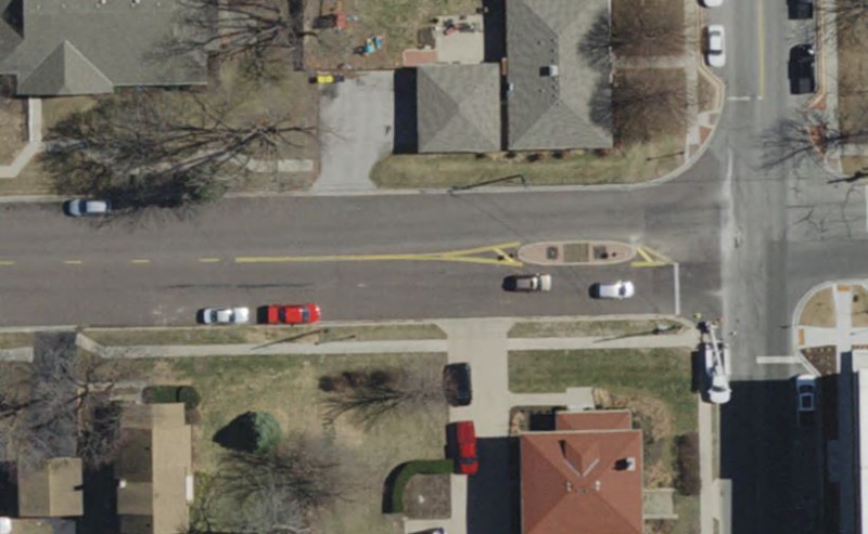
|
| Centerline Transition at Raised Median |
When transitioning from a double yellow centerline to a raised median, the double yellow line should end near the raised nose of the median in order to provide a smooth transition directing traffic away from the median. When the median width, at the widest part, is greater than 6' (measured from the back of curbs), the double yellow centerline should be marked for approaching as well as for departing vehicles.
When the median width, at the widest part, is less than 6' (measured from the back of curbs), the double yellow centerline should be marked for approaching traffic only.
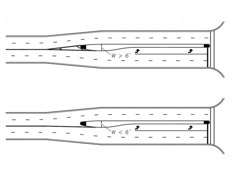
|
| Centerline Transition at Raised Median Based on Width |
Prior to Painted Medians
When transitioning from a broken yellow centerline to a painted median, the painted median should be preceded by a double yellow centerline a minimum of 100’ in length unless there is some engineering reason that limits it to less than 100’, e.g. another intersection. This length should be increased if it places the beginning of the double yellow centerline near the blind side of a crest vertical curve.

|
| Centerline Transition at Painted Median |
Prior to Stop Controlled Intersections
A broken yellow centerline should transition to a double yellow centerline a minimum of 100’ prior to the stop line (or designated stopping point in the absence of a stop line) at an intersection controlled by a stop sign.
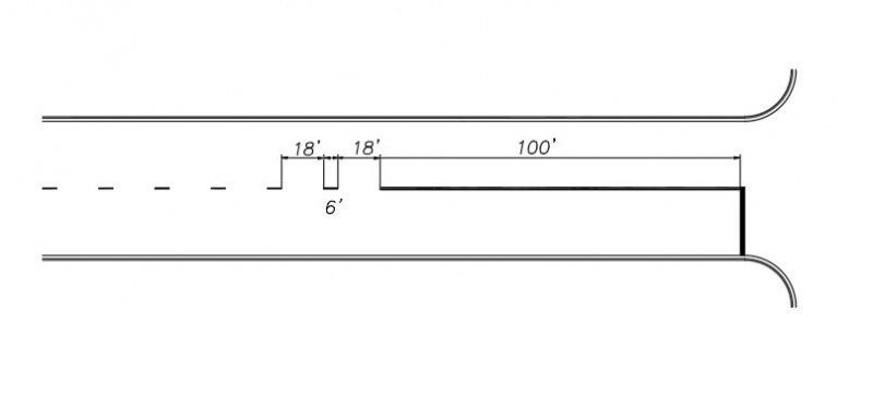
|
| Broken Centerline Transition at Stop Controlled Intersection |
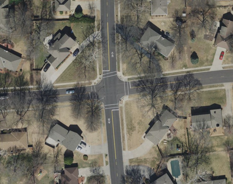
|
| Four-Way Stop at Collector-Collector Intersection |
Special Situations at Intersections
Occasionally, a collector street will turn into a residential street at a two-way stop controlled intersection with another through street segment. The minor collector street leg, which is controlled by a stop sign, will be striped with a broken yellow centerline that transitions to a double yellow centerline 100’ in advance of the stop line. The residential street leg, which is controlled by a stop sign, will not require either a stop line or a centerline.
|
| Special Situations at Intersections |
Special Situations at Midblock Crosswalks
At midblock crosswalks, across roadways with a marked centerline, the broken yellow centerline should transition to a double yellow centerline in advance of the midblock crosswalk for a distance of approximately 50'. A 3' minimum gap should be provided between the double yellow centerline and the marked crosswalk.
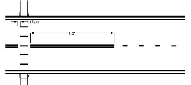
|
| Special Situations at Midblock Crosswalks |
Painted Medians
Painted medians should be used on undivided roadways where it is desirable to provide left turn lanes or separate traffic traveling in opposite directions. For left turn lanes, it is preferable to provide a complete approach taper and a fully shadowed bay taper whenever possible and pavement width permits.
Painted medians also occur in advance of a raised median that has been installed for access control near an intersection approach or in advance of a splitter island of a roundabout. Painted medians should consist of 4” solid double yellow lines with 12” yellow diagonal crosshatch lines. See Yellow Diagonal Crosshatch Lines for more information.
Yellow Solid and Broken Lane Lines
No-Passing Zone Lines
Yellow solid and broken lane lines can be used where crossing the center line markings for passing is permitted for the traffic traveling adjacent to the broken line, but is prohibited for traffic traveling adjacent to the solid line. This centerline marking is typically not used in the City of Overland Park. It requires a passing sight distance study in order to determine where passing is permitted.
Two-way Left Turn Lanes (TWLTL)
Two-way left turn lanes (TWLTL) should consist of 4” solid yellow lines on each side of the travel lane with six foot long 4” broken yellow lines inset inside of the solid yellow lines with 18’ long gaps. The beginning and end of the broken yellow lines should line up with any adjacent broken white lane lines.
The TWLTL should terminate into a left turn lane. The TWLTL lane markings should not extend to intersections. There should be a 42’ long gap between the end of the broken and solid yellow line and the beginning of the 4” solid white lane line for the left turn storage. Two sets of white left turn arrows should be placed 25’ apart measured from the tails of both arrows. The spacing of the arrow sets is dependent on the overall length of the TWLTL. Generally, one set is installed 30’ from the beginning, one set 30’ from the end and one set at approximately the midpoint, but the distance between sets of arrows should not exceed 160’.
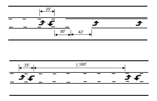
|
| Two-way Left Turn Lanes |

|
Top | Yellow Centerline Markings |
Broken White Lane Lines
Broken white lane line markings should be used on all roadways with two or more adjacent traffic lanes that have the same direction of travel. They shall consist of a 4” wide broken white line with a 6’ stripe and an 18’ gap (3:1 ratio).
The beginning point of broken white lane lines between adjacent lanes of travel on a multi-lane street should line up with each other.
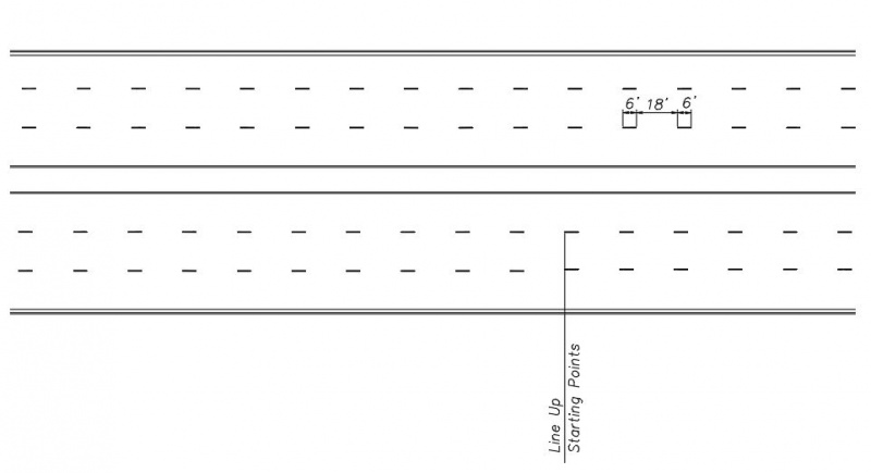
|
| Alignment of Adjacent Broken White Lane Lines |
Ideally, the beginning of a broken white lane line should also line up with the beginning of any adjacent solid white lane line delineating the storage length for a right or left turn lane. However, broken white lane lines should not extend past the stop line.

|
| Alignment of Broken White Lane Line with Solid White Turn Lane Line |
Broken white lane lines should break on each side of a four-legged intersection, comprised of public or private streets, allowing side street traffic to cross without running over the lines. Broken white lane lines should extend through intersections with private and commercial driveways. However, if the main street has a left turn lane into the commercial drive of the development, lane lines should not be marked through the intersection. It would be treated like a standard intersection with public streets.
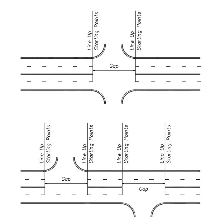
|
| Gaps in Broken White Lane Lines at Intersections |
At tee intersections, the broken white lane lines will continue through the intersection at the top of the tee, but will not extend through the intersection with the lanes closest to the intersecting side street.

|
Top | Broken White Lane Lines |
Broken White Lane Extension Lines
Broken white lane extension lines are used for guiding the traveling public through more complex roadway lane configurations such as:
- Offset through lanes
- Skewed intersections
- Curved roadways
- Where multiple turn lanes are present
- At interchanges where there are extended left turn lanes on the thoroughfare street
- Roundabout circulating lanes
- Where accident history indicates a presence of sideswipe type crashes
The broken white extension line shall be 4” wide and 2’ long with a 4’ gap.
Offset Through Lanes
Depending on the roadway classification and the posted speed, offset through lanes can create situations where white lane extension lines would be beneficial to delineate the travel path of vehicles. Offsets through intersections on a thoroughfare are generally more of a concern than offset through lanes on a collector roadway or a local street. The following gives some guidance on when to install lane extension lines for offset through lanes, but the designer in conjunction with City staff, should use engineering judgment to make the final determination whether to use them or not. Having multiple lines crossing through an intersection can be just as confusing as not having any. Discretion should be used keeping in mind the long term aspects of maintenance, since pavement markings in an intersection are worn down frequently by traveling vehicles.
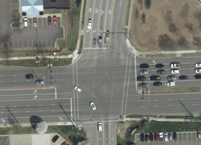
|
| Broken White Lane Extension Lines at Intersections |
When the through traffic lanes on a thoroughfare across an intersection are offset at least one fourth of the width of the lane, white lane extension lines should be considered, especially if the presence of a crest vertical curve near the center of the intersection obstructs the view of the receiving lanes on the opposite side of the intersection. When the offset is one half or more of the width of the lane, the extension lines shall be installed.
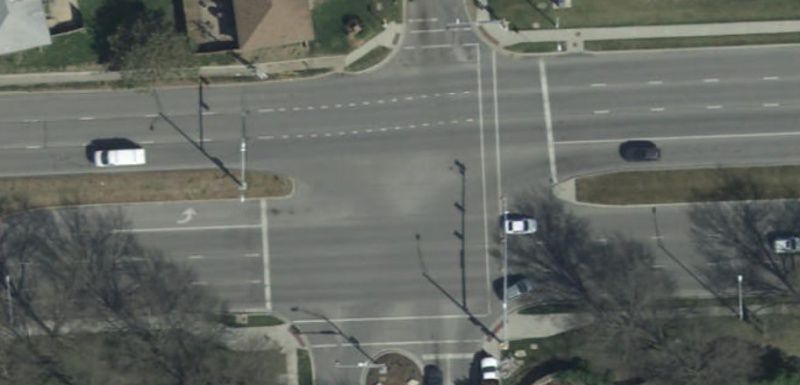
|
| Broken White Lane Extension Lines Through Intersections |
Skewed Intersections
At skewed intersections, where there is a possibility for the opposing turning traffic to overlap paths, white lane extension lines should be considered to delineate the paths regardless of the number of turn lanes or the number of receiving through lanes.
Curved Roadways
Where a vehicle, following a curving curb line, could drift into a left turn or right turn lane, a white extension line should be considered to delineate the path of the vehicle.
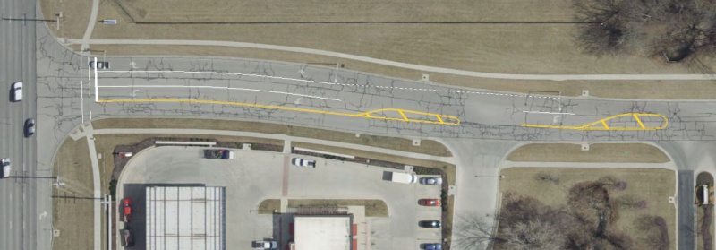
|
| Broken White Lane Extension Lines on Curved Roadway |
Multiple Left or Right Turn Lanes
Broken white lane extension lines are not typically used where the number of turn lanes on the side street is equivalent to the number of receiving through lanes on the major street. For example if two left turn lanes are turning into two through lanes.
They shall be used within an intersection where there are two left turn or two right turn lanes but three or more receiving through lanes. They shall also be used anywhere the number of left turning lanes or right turning lanes is greater than two, regardless of the number of through lanes available for receiving lanes. For example, if a side street has two exclusive left turn lanes and one shared through/left turn lane, the white extension lines shall be installed directing traffic into their respective lanes, even if there are only three through lanes on the main street.
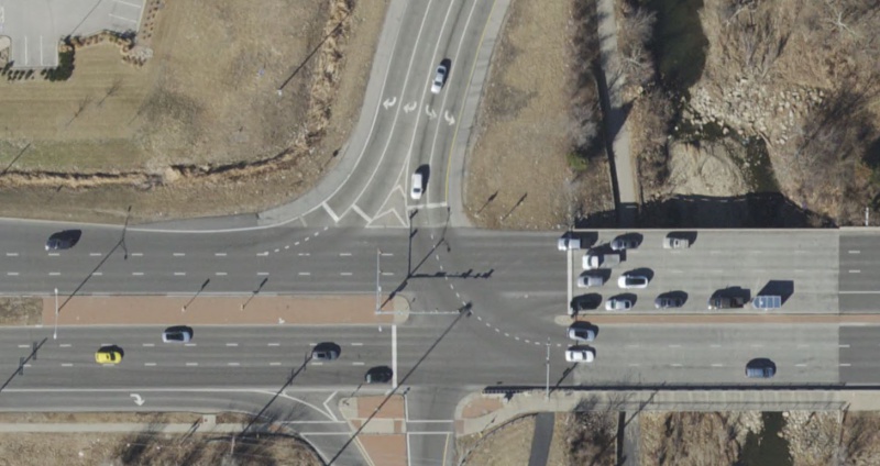
|
| Broken White Lane Extension Line at Multiple Turn Lanes |
At Interchanges with Extended Left Turn Lanes on the Thoroughfare
There are occasions, primarily at interchanges with thoroughfare streets, where there are only two through lanes but the left turn lanes extend upstream of the intersection to increase the storage length. Even though there are only single or dual left turn lanes coming off the ramp and only two receiving through lanes, the broken white lane extension lines should be installed for the ramp traffic so vehicles do not get trapped into the left turn lanes on the thoroughfare.
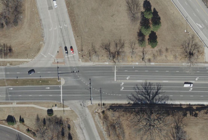
|
| Broken White Lane Extension Line at Interchanges with Extended Left Turn Lanes |
Roundabout Circulating Lanes
Lane extension lines should be installed in the circulating lanes at multi-lane roundabouts opposite the points where lanes from the intersecting roadways enter the roundabout. They should extend toward the exit lanes to direct circulating traffic that is exiting the roundabout to the correct receiving lanes.
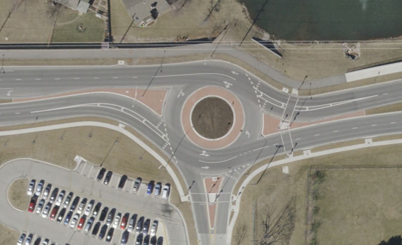
|
| Broken White Lane Extension Line at Roundabouts |
Where Accident Crash History Shows a Need
Lane extension lines should be installed where there is a history of side swipe crashes that could be alleviated by providing more guidance to the driver.

|
Top | Broken White Lane Extension Lines |
Wide Dotted Line
A wide dotted white line marking shall be used as the lane line to separate a through lane that continues beyond the intersection from an adjacent lane that becomes a mandatory turn lane or across the lane(s) entering a roundabout as follows:
Wide Dotted Lane Drop Line
Wide dotted lane drop lines are used for lane drops (trap lanes) where an otherwise through traffic lane turns into a mandatory left turn or right turn lane. Where used, the wide dotted lane drop line shall be 8” wide with a 3’ line segment and a 9’ gap. The wide dotted lane drop line will be accompanied by a 8” wide white solid lane line beginning at the downstream end of the white dotted lane drop line to the stop bar (See White Solid Wide Lane Lines). The length of the dotted lane drop shall be as follows:
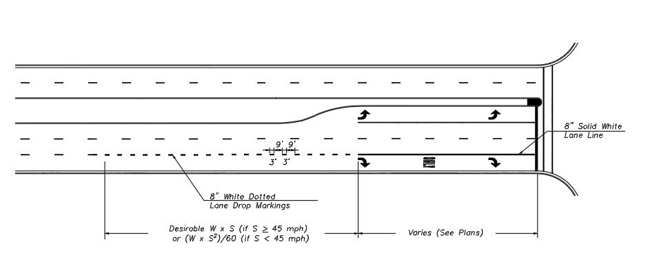
|
| Typical Wide Dotted Lane Drop Lines |
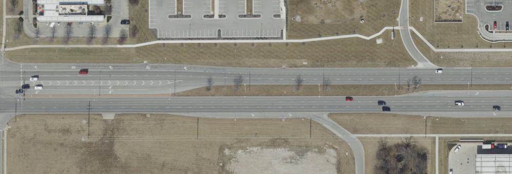
|
| White Dotted Lane Drop Lines with No Restrictions |
Length Based on Posted Speed Limit
For posted speed limits > 45 mph, the length of the wide dotted lane line shall be based on the merge length equation: L = W x S, where W is the width of the lane and S is the posted speed limit, (mph). For posted speed limits < 45 mph, the length of the wide dotted lane line shall be based on the merge length equation L = (W x S2)/60. Exceptions to this rule are as follows:
Spacing Considerations for Closely Spaced Intersections
If the calculated length of the wide dotted lane drop line would extend it into or through an upstream four-legged intersection (whether controlled or uncontrolled), it should begin immediately past the upstream intersection instead of using the full calculated length. The lane drop line should begin no closer to the intersection than the most upstream regulatory or warning sign associated with the lane drop. An R3-7 (R or L) sign should be installed approximately 30’ from the curb return at the intersection. An additional R3-7 (R or L) should be installed at the beginning of the 8" solid wide lane line.
The calculated length of the wide dotted lane drop line can extend through a three-legged T-intersection as long as the major street that has the trap lane is divided with a median. In that case, an R3-7R sign will be installed at the beginning of the wide dotted lane drop line with a street name sign plaque mounted underneath to designate where the lane drops.
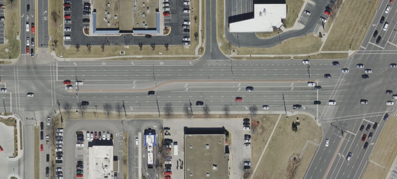
|
| Wide Dotted Lane Drop Lines Thru T-Intersection |
In areas where there is not enough room to achieve the full length without extending through an intersection, a balance should be maintained between the lane drop line and the required storage bay length, based on the observed traffic volumes.
Wide Dotted Lines at Roundabouts
White wide dotted lines should be used across the lane(s) entering a roundabout to mark an extension of the circulatory roadway edge line. They should extend from the splitter island to the exit of the roundabout and be a three foot long, 12” wide line with a three foot gap.
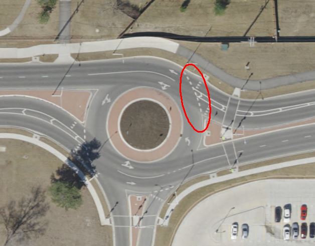
|
| Wide Dotted Roundabout Line |

|
Top | Wide Dotted Line |
Solid White Lane Lines
Solid white lane lines are used where drivers are discouraged from changing lanes. The lane line markings shall consist of a 4” wide solid white line. Solid white lane lines are typically used at intersections to separate a through lane from a mandatory left or right turn lane.
Single Left or Right Turn Lanes
The solid white lane line should extend from the stop line upstream to where the full width of the turn lane begins.
Dual Left or Right Turn Lanes
In the case of dual left or right turn lanes, the inside line should begin at the point of tangency with the median curb, where the full width of the inside lane is available. The outside line should be extended farther upstream to where the lane opening, measured perpendicular from the median curb to the start of the line is 18’, as shown below.
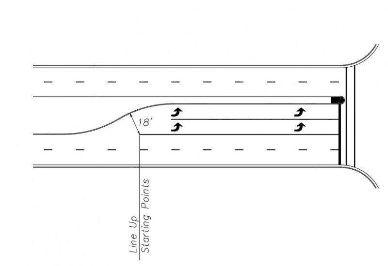
|
| Solid White Lane Lines for Dual Left Turn Lanes |
Continuous Right Turn Lane Exceptions
Where a right turn lane at an intersection would have one or more driveway entrances within the storage bay, the preferred approach is to break the solid white lane line for the driveway and treat them as separate turn lanes. An R3-7(R) sign should be installed at the driveway.
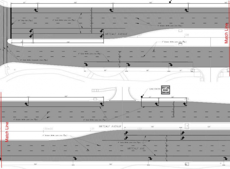
|
| Solid White Lane Lines for Continuous Right Turn Lanes |
If a driveway is located near a signalized intersection such that the distance between the driveway and the intersection does not provide enough storage length, then the solid lane line should be continued through the driveway.
If a driveway occurs at a median break, the lane line should not be carried through the intersection. In the example below, the lane line was continued through the first driveway because the right turn lane was just beginning and not enough storage length was available for the driveway. The R3-7(R) sign was removed for the driveway.
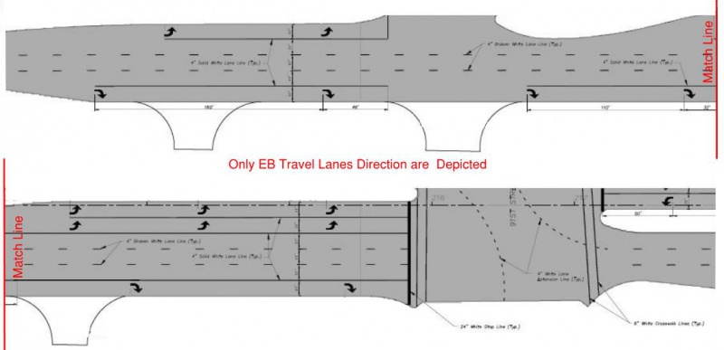
|
| Solid White Lane Line Exception for Continuous Right Turn Lanes |

|
Top | Solid White Lane Lines |
Solid Double White Lane Lines
Solid double white lane lines are used to mark where crossing is prohibited or whenever two lanes of traffic, traveling in the same direction, are separated by a painted median. The most common instance of this occurs between a turn lane and a through lane which is separated by a painted island. This normally occurs when an intersection has offset left turn lanes that are separated from the through lanes to give drivers on opposing approaches a less obstructed view of opposing through traffic. They are also used when an intersection is designed for ultimate double left turn lanes, but one lane has been marked out until sometime in the future when it is required based on traffic volumes. The lane line markings shall consist of a 4” wide solid double white lines separated by a 4” space. White 12” chevron should be installed between the two sets of solid double white lane lines. (See White Chevron Markings) for more information in regard to spacing.
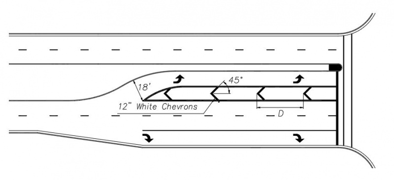
|
| Solid Double White Lane Lines |
White Solid Wide Lane Lines
Solid wide channelization lines are used to form islands where traffic traveling in the same direction is permitted on both sides of the island. They should be 8” wide and used to outline around painted or raised medians as follows:
At Interchange Ramps
Channelizing lines at entrance ramps define the neutral area, directing exiting traffic at the proper angle for smooth divergence onto the ramp. They should be used to outline raised islands or used for painted islands that separate interstate ramp movements from through movements on thoroughfare streets.
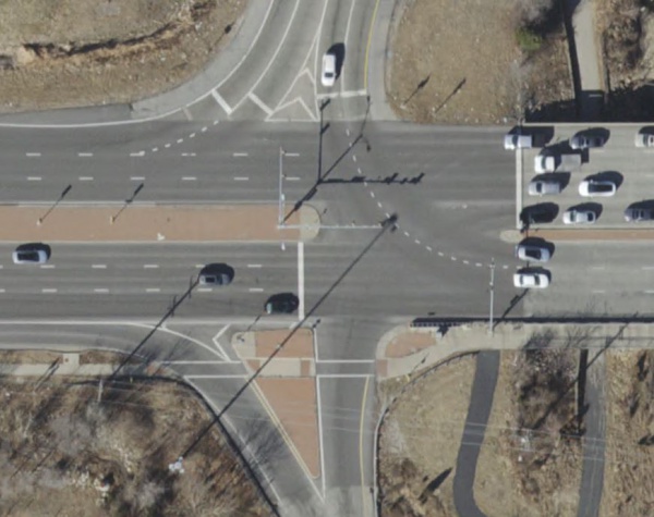
|
| White Solid Wide Lane Lines at Interstate Ramp Islands |
At Free Flow Right Turn Lanes
They should also be used to outline the raised medians for free flow right turn lanes on City streets.
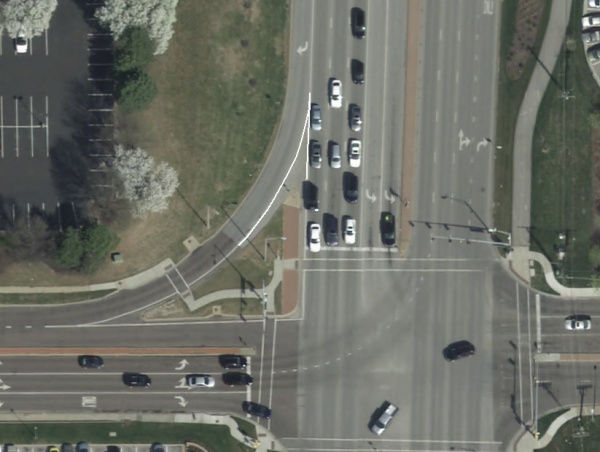
|
| White Solid Wide Lane Lines Around Islands at Intersections |

|
Top | White Solid Wide Lane Lines |
White Edge Lines
Edge lines are 4” wide lines that are used to delineate the right or left edges of roadways that have paved or turf shoulders. If they are on the left hand side of the roadway, they shall be yellow. They shall be white if they are on the right hand side of the roadway. Edge lines shall not be continued through intersections or major driveways that consist of turn lanes entering from the major street. But they would extend through minor driveways. They should be placed on rural thoroughfares and collectors with a traveled way of 20’ or more and an average daily traffic (ADT) of 3,000 vehicles per day or greater. If a bicycle lanes is marked on the outside portion of the traveled way, the edge line that would mark the outside edge of the bicycle lane should be omitted.
In the case of turf shoulders, the edge line shall be inset to allow a minimum of 4” from the edge of the asphalt roadway to the edge of the line.
Edge Lines on Diverging Diamond Interchanges (DDI’s)
Edge lines on diverging diamond interchanges (DDI’s) require clarification. The two directions of travel are separated by either a raised median or bridge rails. This would normally require the edge line separating the two directions of travel to be yellow. However, this violates the rule that yellow lines shall always be on the left hand side of the driver. Therefore, the pavement for the two directions of travel are treated as separate, one-way roadways. Therefore, the edge lines will be yellow on the left side and white on the right side for drivers traveling in each direction.
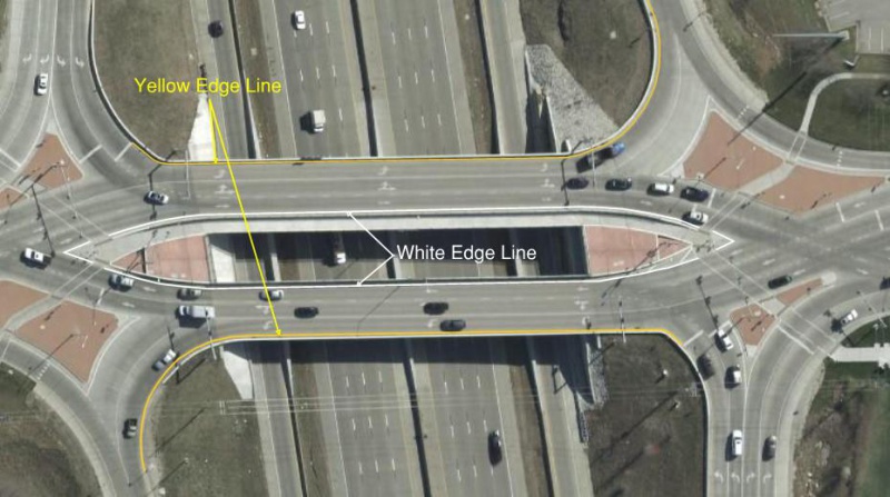
|
| Edge Lines for Diverging Diamond Interchanges (DDI's) |
Edge Lines on Bridges
Edge lines should be installed across all bridges, regardless of whether the roadway approaches to the bridge consist of curb and gutter or shoulders. The edge line should be offset from the bridge rail to provide a horizontal buffer space for vehicles and to maintain a constant lane width across the bridge. The solid white edge line across a bridge should be eliminated if a bicycle lane exists. The solid white line on the left side of the bicycle lane will act as the vehicle edge line.
White Stop Lines
Stop lines indicate the point behind which vehicles are required to stop in compliance with a STOP sign. Stop lines may be either 12” wide or 24” wide, and shall be based on the stop sign size as required by the Manual on Uniform Traffic Control Devices (MUTCD). If the STOP sign size should be 30”, the stop line should be 12” wide . If the STOP sign size should be 36” or larger, the stop line should be 24” wide. At all-way stop controlled intersections, the stop bars and stop signs shall be the same size on all approach legs and based on the largest sign size required at the intersection according to the MUTCD and Overland Park Stop Sign Guidelines flowchart. At signalized intersections, the stop line on all approaches should be 24” wide. The following are general guidelines for white stop lines. (Refer to Crosswalk and Stop Line Usage) for specific guidance regarding when to install them.
Stop Lines in Conjunction with Crosswalks
In general, a stop line should always be installed in advance of a crosswalk on an approach that is controlled by stop sign.
Stop Lines for Standard Intersections Without Skew
In general, the stop lines should typically be perpendicular to the lane of travel and extend across all lanes as a continuous straight line. Stop lines shall be installed such that they are not located in the vehicle path of left turn movements from the side street approach. This is particularly critical where there is no median separating opposing through lanes. Where raised medians exist, the stop line for the left turn lane should generally be located at the median nose.
The minimum separation from the trailing edge of the stop line to the leading edge of the crosswalk line shall be 4’. If the distance from the crosswalk line or theoretical crosswalk line is greater than 15', consider staggering the stop lines for the through lanes closer to the intersection, to minimize this distance. This occurs when the median nose is pulled back to accommodate left turning vehicles from the side street. Do not stagger the stop line if the distance between the staggered stop line for the left turn lanes and the through lanes would be less than 5’, even if the distance exceeds 15'.
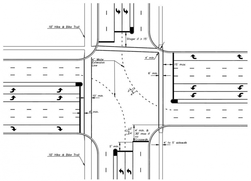
|
| Stop Lines at Intersections without Skew |
Stop Lines for Skewed Intersections
In the case of severely skewed intersections, several things should be taken into consideration. The stop line should generally be installed parallel to the crosswalk lines as long as the vehicle position for the farthest right hand lane is closer to the intersection than the left turn vehicle to avoid obscuring the intersection sight distance for right turn vehicles making right turns on red signal indications. Where raised medians exist, the stop line for the left turn lane should generally be located at the median nose. The minimum separation from the trailing edge of the stop line to the leading edge of the crosswalk line shall be 4’. If the distance from the crosswalk line or theoretical crosswalk line is greater than 15', consider staggering the stop lines for the through lanes closer to the intersection, to minimize this distance. This occurs when the median nose is pulled back to accommodate left turning vehicles from the side street. Do not stagger the stop line if the distance between the staggered stop line for the left turn lanes and the through lanes would be less than 5’, even if the distance exceeds 15'. On the other legs, install the stop lines perpendicular to the vehicle path. The distance from the stop line to the crosswalk line for the farthest right vehicle should be 4' minimum. The distance for the remaining lanes is not controlled by a maximum distance.
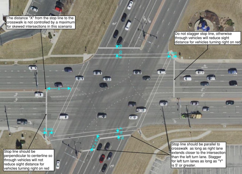
|
| Stop Lines at Intersections with Skew |
Stop Line Location Coordination with Signal Detection Systems
When placing stop lines at signalized intersections, care should be taken to determine what method of vehicle detection is being used. If induction loops are currently being used, the stop line should be located such that the first diamond in the loop extends at least half-way past the stop line into the intersection. If video detection or radar detection is currently being used, it is possible to change the detection zones. The engineer should be contacted to determine if a change in the detection zone is required or if a change in the stop line location can be accommodated.

|
Top | White Stop Lines |
White Crosswalk Lines
Crosswalk markings provide guidance for pedestrians who are crossing the roadway by defining and delineating paths on approaches to and within signalized intersections, and on approaches to other intersections where traffic stops or yields. Crosswalks help to alert road users of a designated pedestrian crossing point across roadways at locations that are not controlled by traffic control signals or stop or yield signs. At non-intersection locations, crosswalk markings legally establish the crosswalk.
Crosswalk markings are classified as either basic (transverse) or high-visibility. Basic crosswalk markings consist of two transverse lines. High visibility markings, sometimes called a longitudinal bar or a continental crosswalk, consist of longitudinal lines parallel to traffic flow with or without transverse lines. The following are general guidelines for white crosswalk lines. Refer to Crosswalk and Stop Line Usage for specific guidance regarding when to install them.
Basic Crosswalk Markings
All crosswalk markings in the City of Overland Park will be considered basic crosswalk markings, unless the criteria listed in the table for high-visibility crosswalk markings is met.
Basic crosswalk markings shall consist of two 6" wide white transverse lines extending from curb to curb across the full width of the roadway to be crossed. The gap between the lines should not be less than 6 feet, measured between the inside edges of each of the lines. When the crosswalk extends a 4’ sidewalk through the intersection, the width of the crosswalk should be 6’. When the crosswalk extends a 10’ bike path through the intersection, the width of the crosswalk should be 10’. Where an Overland Park-maintained shared-use path crossses a roadway, crosswalk markings shall be installed.
If crosswalk lines from adjacent legs of the intersection intersect prior to the curb line, a 45 degree angled crosswalk line should be used near the ramp location to maintain a 4’ minimum distance from the back of curb to the angled portion of the crosswalk.
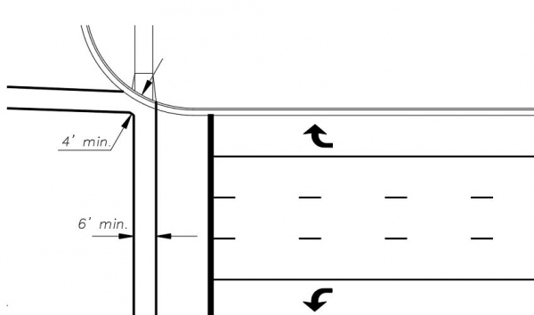
|
| Intersection of Adjacent Basic Crosswalk Lines |
High-Visibility Crosswalk Markings
For added visibility at locations that have a significant amount of pedestrian activity, especially within the downtown district of Overland Park; at any midblock or uncontrolled through movement locations; including Pedestrian Hybrid Beacon (aka HAWK signal); at all roundabout crosswalks; or where crashes with pedestrians have occurred, high visibility crosswalk markings should be used instead of the standard crosswalk lines.
At intersections, if one approach warrants a high-visibility crosswalk, any other approach that warrants a crosswalk should also be a high-visibility crosswalk, even if it does not necessarily meet the criteria in the High-Visibility Crosswalk Criteria table shown below.
When the crosswalk extends a 10' shared-use path or trail through an intersection, the width of the crosswalk should be 10'.
When used, the lines should be 24 inches wide and separated by gaps not less than 3’ and not more than 5’ based on the lane width. The design of the lines and gaps should be spaced as evenly as possible across the lanes of vehicle travel and avoid the wheel paths as much as possible. On undivided roadways, the spacing for 12’ and 11’ lanes is shown below.
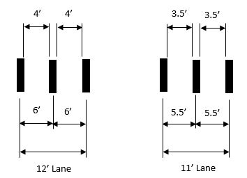
|
| High-Visibility Crosswalk Detail |
On divided roadways, some variation in the gaps between markings is acceptable to accommodate for the width of the median. See the examples below.
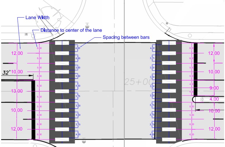
|
| High Visibility Crosswalk on Divided Roadways |
The high-visibility crosswalk markings should generally be placed parallel to the direction of vehicle travel and perpendicular to the travel of the pedestrian. However, at skewed intersections or intersections with irregular entry streets, the configuration of the markings may have to be arranged more aesthetically up to 45 degrees.
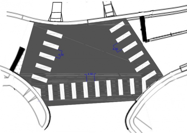
|
| High Visibility Crosswalk At Irregular Intersections |
The following criteria will be used for marking pedestrian, bicycle, trail, and golf cart crossings which have been approved:
High-Visibility Crosswalk Criteria Pedestrian Hybrid Traffic (HAWK) Signal Condition High-Visibility Crosswalk Markings Stop Line Any Yes Yes Traffic Signal, Stop or Yield Sign Adjacent to Elementary or Middle School Condition High-Visibility Crosswalk Markings Stop Line or Yield Line No Crossing Guard No1 See Specific Criteria Crossing Guard Assigned Yes See Specific Criteria Downtown Overland Park Condition High-Visibility Crosswalk Markings Stop or Yield Line Any Yes See Specific Criteria Mid-Block Crossings or Uncontrolled Through Movements Condition High-Visibility Crosswalk Markings Yield Line Pedestrian or School Crossings2 Yes If Multi-Lane Approach Trail Crossings3 Yes If Multi-Lane Approach Golf Cart Crossing Yes No Roundabouts Yes Yes
1Unless an adjacent crosswalk at the same intersection warrants a high-visibility crosswalk.
2If the posted speed limit is 40 mph or greater at a non-intersection locatoion, the minimum width of the crosswalk shall be 8 feet.
3Applies to any street classification and does not need to meet volume criteria to be marked or signed. If the posted speed limit is 40 mph or greater at a non-intersection location, the minimum width of the crosswalk shall be 8 feet.
Crosswalk and Stop Line Usage
The following table explains when stop lines and crosswalk lines should be installed at intersections. If a street has centerline markings, it should have a stop line.
Crosswalk and Stop Line Usage Guide Intersection Description Installation Guidelines Approach Street Cross Street Intersection Control5 No. of Lanes on Approach Stop Lines Crosswalks White Lane Lines Turn Arrows Residential Residential TWSC 1 No1 No2 No No Residential Residential TWSC > 1 Yes No2 Yes Yes Residential Residential AWSC Any Yes No2 Maybe3 Maybe3 Residential Collector4 TWSC 1 No1 No2 No No Residential Collector4 TWSC > 1 Yes No2 Yes Yes Residential Thoroughfare TWSC 1 No1 No2 No No Residential Thoroughfare TWSC > 1 Yes No2 Yes Yes Collector4 Collector4 TWSC 1 Yes No2 No No Collector4 Collector4 TWSC > 1 Yes No2 Yes Yes Collector4 Thoroughfare TWSC 1 Yes No2 No No Collector4 Thoroughfare TWSC > 1 Yes No2 Yes Yes
1Do not install stop line unless there is a warranted and marked crosswalk. (See Note 2 below)
2Do not install crosswalk pavement markings unless there is a warranted crossing determined by a pedestrian study or a shared-use path is present.
3TWSC = Install lane lines and arrows when there is more than one approach lane
4The "Collector" designation also includes commercial streets and apartments streets that are 36' wide (Bk-Bk) w/ speed limit 30 mph
5TWSC = Two-Way Stop Control; AWSC = All-Way Stop Control
Signalized Intersections
White crosswalk lines are generally installed on every approach at a signalized intersection unless there are no sidewalks or curb ramps on the corners.
Roundabout Crosswalk Markings
On an approach to a circular intersection controlled by a Yield sign and at uncontrolled exits, crosswalks shall be a minimum of 20 feet from the edge of the circulatory roadway.
Mid-block Crosswalks
Do not install crosswalk lines unless there is a warranted crossing determined by a pedestrian count or engineering study. The engineering study should consider the number of lanes, the presence of a median, the distance from adjacent signalized intersections, the pedestrian volumes and delays, the average daily traffic (ADT), the posted or statutory speed limit or 85th-percentile speed, the available gaps, the geometry of the location, the possible consolidation of multiple crossing points, the availability of street lighting, and other appropriate factors. If there is a warranted mid-block crossing, install high-visibility crosswalks. If the mid-block crossing is a multi-lane approach, also install yield lines. At non-intersection crosswalks where the posted speed limit is 40 mph or greater, the minimum width of the crosswalk shall be 8'.
Crosswalks at City Limits
Where crosswalks on city limits are shared with adjacent cities, the city standard with the most visible crosswalks should apply.

|
Top | White Crosswalk Lines |
White Yield Lines
Yield lines are used to indicate the point behind which vehicles are required to yield in compliance with a Yield sign, Yield Here To Pedestrians sign or other appropriate sign. Yield lines consist of a row of solid white isosceles triangles pointing toward approaching vehicles extending across approach lanes to indicate the point at which the yield is intended or required to be made. They should be used in advance of mid-block crosswalks, in advance of a crosswalk on approaches controlled by a yield sign, and on approaches to a roundabout.
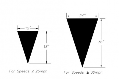
|
| Yield Line Detail |
Yield Lines in Conjunction with Crosswalks
In general, a yield line should always be installed in advance of a crosswalk on an approach that is controlled by a yield sign.
At Mid-block Crosswalks
At a mid-block crosswalk, they should be placed between 20’ and 50’ in advance of the nearest crosswalk line and parking should be prohibited in the area between the yield line and the crosswalk line. The size of the yield line depends on the posted speed limit on the street. For speeds greater or equal to 30 mph, the size should be 24” x 36”. For speeds less than 30 mph, the size should be 12” x 18”. The yield lines should be spaced evenly across all lanes of pavement. Maintain a minimum distance of 12” between adjacent markings and 6” away from lane lines, centerlines and edge of pavement.
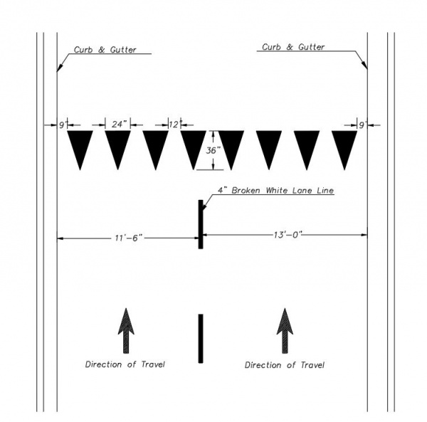
|
| Mid-block Yield Lines on Divided Thoroughfare Streets |
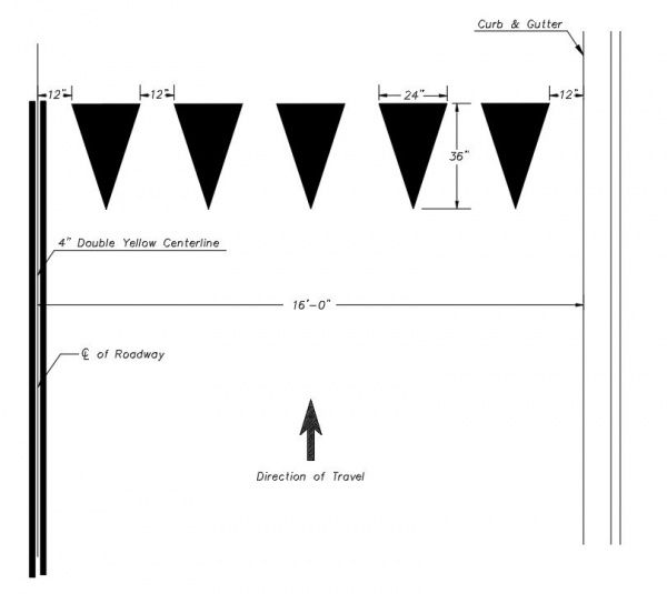
|
| Mid-block Yield Lines on Collector Streets |
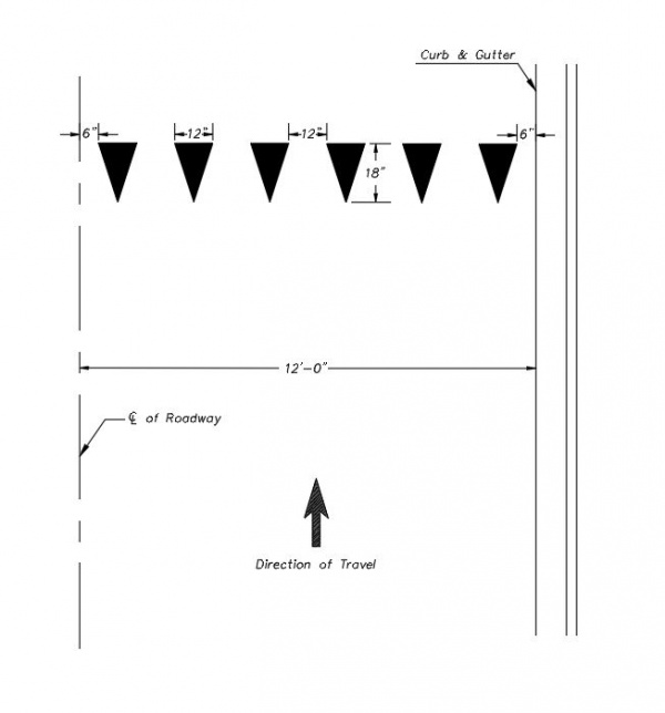
|
| Mid-block Yield Lines on Residential Streets |
At Approaches to Roundabouts or Mini Roundabouts
At approaches to a roundabout or mini roundabouts, the yield lines should be placed near the 12” wide x 3’ long white dotted extension line of the circulatory roadway edge. There should be a minimum of 20’ beyond the crosswalk line to allow a full vehicle storage length. The yield lines should be 24” x 36” separated by 12” at the base of the triangle.
At Approaches to Traffic Calming Circles
At approaches to neighborhood traffic circles designed to calm traffic, the yield lines should be placed near the 6” wide x 2’ long white dotted extension line of the circulatory roadway edge. The yield lines should be 12” x 18” separated by 12” at the base of the triangle.
In Conjunction with Bicycle Lanes
At mid-block crosswalks that pass through bicycle lanes, a yield line should be placed within the bicycle lane, since bicycles are required to obey the same rules of the road as vehicles. For streets with posted speed limits of 30 mph and greater, one yield line shall be placed in the center of the bicycle lane. For streets with posted speed limit less than 30 mph, two yield lines shall be placed in the bicycle lane.

|
Top | White Yield Lines |
White Arrow Symbols
Turn arrow markings on the pavement are used for the purpose of guiding, warning, or regulating traffic. They consist of either lane-use assignment arrows, e.g. left turn, right turn, or combination thru/turn arrows, and merge arrows. Lane-use assignment arrows and merge arrows are sized and installed as shown on the standard details.
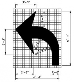
|
| Turn Arrow Detail |
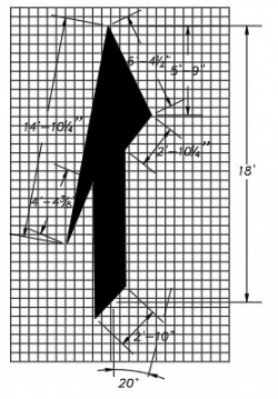
|
| Merge Arrow Detail |
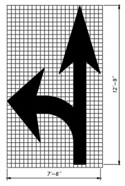
|
| Combination Turn-Straight Arrow Detail |
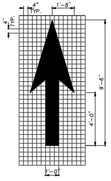
|
| Straight Arrow Detail |
Turn Arrows for Lane Assignments
Lane-use assignment arrows should be used in lanes designated for the exclusive use of a turning movement and consist of right or left turn arrows, straight arrows, or combination straight/turn arrows. Turn arrows should be installed in all right or left turn lanes. The first arrow on the up-stream end of the turn bay should be installed such that the tail of the arrow is aligned with the beginning of the solid white lane line. If there are dual turn lanes , the arrows in each adjacent lane should be aligned. In this case, the turn arrows should be positioned based on the shortest turn lane and placed with the tail of the arrow at the beginning of the shortest solid white lane line. The spacing of the remaining arrows should be based on the overall length of the turn bay, according to the table in the standard details. In the case of multiple turn lanes, the spacing should be based on the shortest storage bay length.
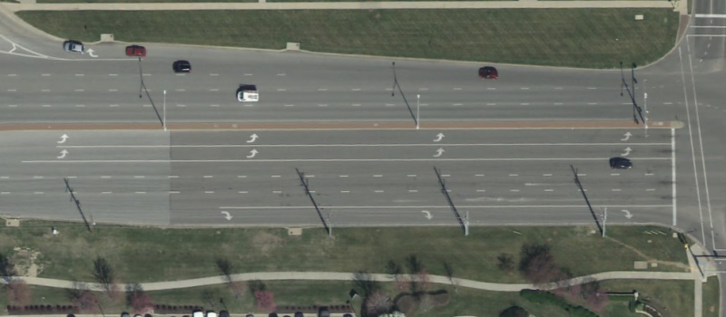
|
| Turn Arrow Positioning in Dual Turn Lanes |
Combination straight/turn arrows are used when it is allowable to either turn or travel straight through the intersection.
Straight Arrows for Lane Assignment
Straight arrows should be used in advance of an interchange where the left lane to enter onto the interstate ramp occurs in advance of the previous intersection in an attempt to maximize vehicle storage. The straight arrow is an indication that the lane extends past the previous intersection but will end up in a left turn lane at the interchange.
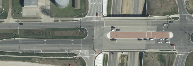
|
| Straight Arrows for Extended Turn Lanes at Interchanges |
Straight arrows are also appropriate for through lanes at diverging diamond interchanges (DDI’s) to assist vehicles in negotiating the interchange. In this scenario, the through arrows are not necessarily located at the beginning of the solid white lane line. Instead, they are located near the stop lines and at locations to provide positive guidance to vehicles at the point of divergence from the usual lane positions.
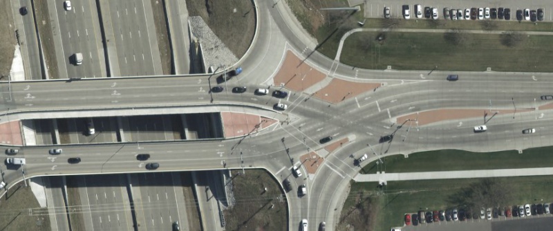
|
| Straight Arrows at DDI Interchanges |
Straight arrows on through approach lanes are typically not used at standard intersections unless it is apparent that driver confusion exists and the installation of a through arrow would help alleviate the problem. For example, if there is only one through lane on the approach but then widens out to include left turn lanes and right turn lanes. In this situation, all lanes have solid white lane lines on each side of them.
Lane-Reduction Transition Merge Arrows
Lane-reduction transition merge arrows are used where the number of through lanes is reduced because of narrowing of the roadway. This generally occurs where a four-lane divided thoroughfare transitions to a two-lane undivided roadway at the project construction limits. Lane-reduction transition markings are not used for lane drops.
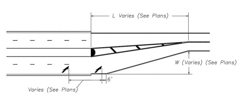
|
| Lane-Reduction Transition Merge Arrows |
Where the posted speed is 45 mph or greater, the transition length should be L = W x S. For posted speeds less than 45 mph, L = WS2/60. Where S = the posted speed in mph and W = the lane offset in feet. The broken white lane line markings should be discontinued ¼ the distance downstream of the Lane Reduction warning sign based on the requirements of the MUTCD. The first lane-reduction transition merge arrow should be placed at the same location. An additional arrow should be placed 6’ upstream of the beginning of the pavement width transition, measured from the tip of the arrow. Coordination should occur with the roadway engineers to insure the taper lengths are long enough to accommodate the required distances.

|
Top | White Arrow Symbols |
White ONLY Markings
The “ONLY” pavement marking symbol should be used exclusively for trap lanes, where the lane was a through lane at the previous intersection and drivers must now turn left or right because the lane does not continue through. The “ONLY” markings will be spaced alternately with either right or left turn arrows at a distance based on the length of the solid white lane line. See the table in the standard details for arrow and “ONLY” symbol spacing.
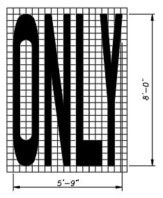
|
| ONLY Marking Detail |
White Railroad Crossing Markings
Pavement markings in advance of a railroad grade crossing shall consist of an “X”, the letters “RR”, no-passing zone markings, transverse lines and dynamic envelope markings as outlined below and according to the standard details. Identical markings shall be placed in each approach lane to grade crossings.

|
| Railroad Crossing Markings |
Railroad Crossing Symbol
The railroad crossing symbol shall consist of a white “X” with a white “R” on either side of it. The lines making up the “X” shall be 16” wide. The height of the “X” shall be 20’ tall and 8’ wide, which should encompass both “R” markings. The height of each “R” shall be 6’. The railroad crossing symbol shall be located between the transverse lines as described below.
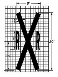
|
| RR Xing Symbol |
Railroad Stop Line
A 24” wide, white stop line shall be installed across the approach lanes to a railroad grade crossing to indicate the point behind which vehicles might be required to stop. It should be placed at a right angle to the traveled way and should be placed no closer than 15 feet in advance of the nearest rail. For skewed crossings, the nearest rail could be that which is closest to the opposing lane of traffic.
Railroad Transverse Lines
Two additional 24” wide, white transverse lines shall be placed across each lane on the approach of a railroad grade crossing at both the upstream and downstream side of the railroad crossing symbol. They shall be located 15’ from the leading edge of the transverse line to the bottom of the X, and from the top of the X to the far edge of the transverse line, respectively. The distance from the far edge of one transvers line to the far edge of the other should be 50’.
Dynamic Envelope Markings
Dynamic envelope markings are 4” white lines placed across all lanes of traffic and parallel to the railroad tracks to define the clearance required for the train and its cargo overhang due to any combination of loading, lateral motion, or suspension failure. They should be placed 6’ from the nearest rail.
White Chevron Markings
White chevron markings are used between two lanes of traffic traveling in the same direction to discourage travel in certain paved areas such as flush medians between double solid white lane lines. The chevrons should be installed with the point of each facing toward approaching traffic and slanting to the left and right away from of approaching vehicles. They should be spaced equal to the posted speed limit, in feet, e.g. 35’ for 35 mph. This spacing should be modified as necessary to have at least two chevrons. If the overall width between the painted lines is less than 6’ or the overall length is less than 20’, the diagonal crosshatch lines should be omitted. (See Solid Double White Lane Lines).
Diagonal Crosshatch Markings
Diagonal crosshatch markings are used to discourage travel on certain paved areas such as flush medians, shoulders, gore areas, between solid double yellow centerline markings or between white channelizing lines. They should be 12” wide and spaced equal to the posted speed limit, in feet, e.g. 35’ for 35 mph. If the overall width of the painted median or hatched out area is less than 4’ or the overall length is less than 20’, the diagonal crosshatch lines should be omitted.
Yellow Diagonal Crosshatch Markings
Diagonal crosshatch markings shall be yellow when used on the left-hand side of divided roadways and on the left-hand shoulders of one-way streets or ramps. They shall be installed between double solid yellow lines separating traffic traveling in opposing directions or along the center median that separates traffic traveling in opposing direction. The yellow diagonal crosshatch lines should be slanted away from traffic in the adjacent travel lanes from the bottom left to the top right to approaching vehicles.
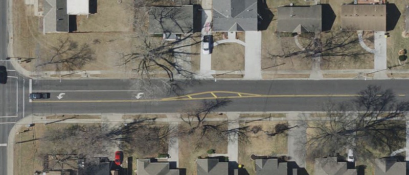
|
| Yellow Diagonal Crosshatch Lines |
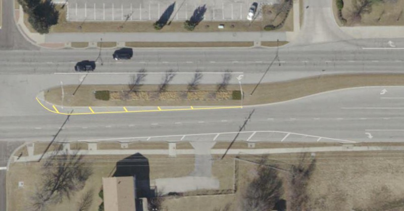
|
| Yellow and White Diagonal Crosshatch Lines |
White Diagonal Crosshatch Markings
White diagonal crosshatch markings shall be installed when traffic lanes are striped out on the right hand side of the roadway. They shall be slanted away from traffic in the adjacent travel lane from the bottom right to the top left to approaching vehicles.

|
Top | White ONLY Markings |
Bicycle Markings
Bicycle markings indicate the separation of the lanes for road users, assist the bicyclist by indicating assigned travel paths, indicate correct lateral positioning in a shared lane and provide advance information for turning and crossing maneuvers. The various markings for bicycle lanes or shared lanes will consist of bicycle lane symbols and bicycle lane arrows or sharrow markings, respectively.
Bicycle Lane Lines
Bicycle lanes shall be installed where a separate portion of the roadway is designated for preferential use by bicycles. Bicycle lanes shall be defined with a 4” longitudinal solid white line desirably placed 5’ (4’ minimum) from the edge of the pavement exclusive of a curb and gutter. At intersections, the bicycle lane should always be located between the through lane and right turn lanes or the through lane and left turn lanes. Broken white extension lines shall be used on both sides of the bicycle lane through the transition area of a right turn lane. Once the full width of the right turn lane is developed, there shall be a 4” solid white lane line on each side of the bicycle lane that extends to the stop line.
If a bicycle lane extends across a bridge, omit the standard white edge line which would end up on the right side of the bicycle lane.
Bicycle lanes that are installed in conjunction with trap turn lanes require special treatment combined with the proper lane drop lines. The bicycle lane markings should stop 150’ before the beginning of the trap lane. Through bicycle lane markings should resume to the left of the right turn only lane or to the right of a left turn only lane. See the standard details for more information.
The length of the right or left trap lane storage on one side of the bicycle lane, identified by the 8” solid white lane line, shall extend back from the stop bar exactly 100'. One cycle of “Arrow - ONLY – Arrow” pavement markings shall be placed in the trap turn lane based on the spacing requirements listed in the standard details for a 100' storage length. The 8” solid white lane line will be extended upstream with 48’ of 4” broken white lane extension line; followed by a 54’ area that is unstriped; followed by another 48’ of 4” broken white lane extension line, as indicated in the standard details. The other side of the bicycle lane shall be a solid 4” white lane line extending 250’ upstream from the stop bar. This line will be extended farther upstream by a 3'x9' broken white trap lane line marking. (See Wide Dotted Lane Drop Line) for more information regarding the length of the trap lane line markings.
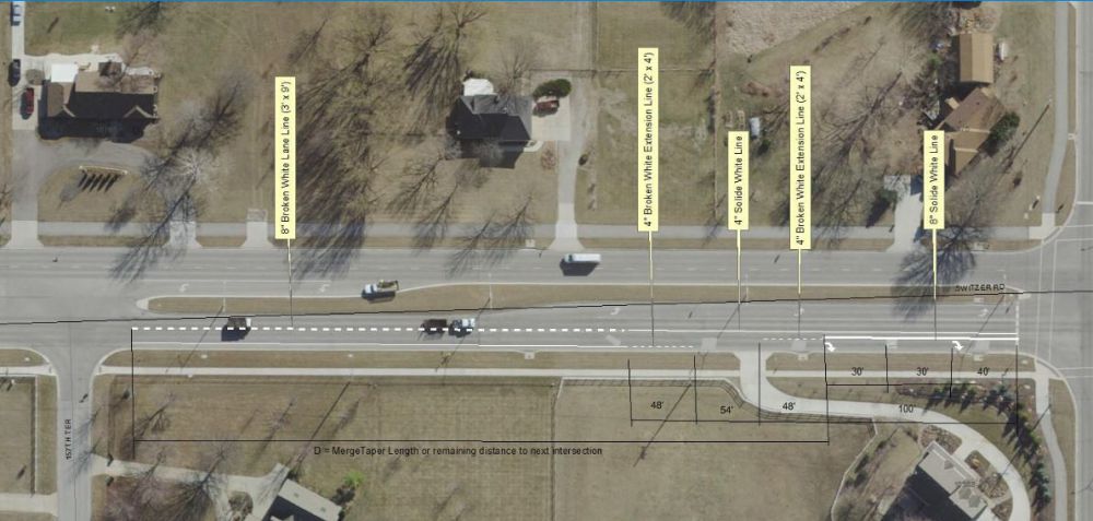
|
| Bicycle Lane and Trap Lane Markings |
Bike lane lines remain solid at commercial driveways and school driveways. Bike lane line shall be cut at public and private streets.
Bicycle Lane Symbols
A bicycle lane symbol depicts a side view of a bicycle. The symbol adopted by the City of Overland Park is just the symbol of the bicycle and not the bicycle/rider combination and shall be the standard bicycle for both the sharrow and the bicycle lane markings. Do not install bicycle lane markings (bicycle symbol or arrow) if there is an adjacent bike path next to the roadway. Only install the solid 4” white line. The bicycle symbol will be placed:
- At the beginning of a bicycle lane and at periodic intervals along the bicycle lane based on engineering judgement.
- They are not required after every intersection, but should be placed after each intersection with a thoroughfare or collector roadway.
- They will also be placed on the approach prior to stop controlled or signal controlled intersections.
Where right turn lanes exist, the bicycle lane symbol will be placed across from any turn arrows spaced according to the table in the standard details. If there are no turn lanes, the bottom of the bicycle symbol shall be placed 30’ in advance of the leading edge of the stop line. When it is placed after an intersection, it should be located such that the distance from the beginning of the solid bicycle lane line to the bottom of the symbol is 25’. The bicycle lane symbol shall be 6’ tall and 3’-4” wide.
Bicycle Lane Arrows
Bicycle lane arrows shall accompany the bicycle lane symbol when it is located in a designated bicycle lane. The straight arrow shall be 2’ wide and 6’ long and placed 6’ after the bicycle lane symbol. Turn arrows shall be 3’-6” wide and 4’-7” long.
Bicycle Sharrows
Shared lane markings (Sharrows) may be used to assist bicyclists with lateral positioning in a shared lane with on-street parking in order to reduce the chance of a bicyclist’s impacting the open door of a parked vehicle or when lanes are too narrow for side by side travel by a vehicle and bicycle in the same traffic lane. They consist of the bicycle symbol and two white chevron markings placed above. The chevrons should begin 2” below the top of the handle bars and be 3’-6” high, based on the standard details. They should not be placed on roadways that have a posted speed limit above 35 mph.
If used in a shared lane with on-street parallel parking, sharrows should be placed so that the centers of the marking are centered in the driving lane. When parking does not regularly occur, the sharrow marking should be placed such that the centers of the marking are 2’-6” from the gutter lip. If the driving lane is less than 14' wide on a street without parallel parking, the sharrow marking should be at least 2'-6" from the gutter lip or 4' from the edge of pavement where there is no curb. See the Flowchart for Placing Sharrow Markings on Collector Streets for more guidance on where to place sharrow markings. They should be placed after an intersection, 25’ beyond the radius point on the curb return and thereafter between 250’ and 500’ based on engineering judgement.
If the collector street transitions to one through lane in each direction and one left turn lane, use sharrow markings in the three lane section, even if the rest of the street meets the criteria for bicycle lanes.
Parking Space Markings
Parking space markings are used to encourage more orderly and efficient use of parking spaces and identify locations where parking is permitted as well as where parking is prohibited. All parking space lines shall be 4” solid white lines.
Perpendicular Parking Space Markings
Perpendicular parking space markings shall be oriented 90 degrees to the driving aisle or the curb. Standard parking space lines shall be placed such that the center to center distance is 9’ wide. Any usable gutter area can count toward the width requirements. The depth of the parking space varies. Accessible perpendicular parking spaces for vehicles shall be 8’ wide with a 5’ access aisle consisting of a 4” wide, white outline with 4” wide, white diagonal crosshatch lines oriented at 30 degrees counter-clockwise to the curb. Van accessible spaces shall be 8’ wide with an 8’ access aisle .
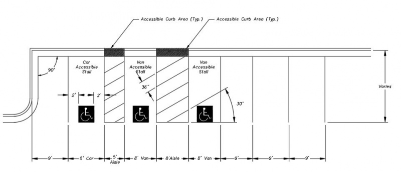
|
| Perpendicular Parking Space Markings |
Angled Parking Space Markings
Standard angled parking space markings either make an angle with the curb of 45 or 60 degrees. The perpendicular distance between standard parking space lines shall be 9’, measured from the center of the lines. Any usable gutter area can count toward the width requirements. The depth of the parking space varies. Accessible angled parking spaces for vehicles shall be 8’ wide with a 5’ access aisle consisting of a 4” wide, white outline with 4” wide, white diagonal crosshatch lines oriented at 60 degrees counter-clockwise to the curb. Van accessible spaces shall be 8’ wide with an 8’ access aisle.
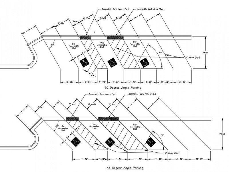
|
| Angled Parking Space Markings |
Parallel Parking Space Markings
Parallel parking spaces shall be designated with tic marks when parallel parking spaces are provided along a street. They shall be a white “plus” (+) symbol with 4” wide strokes. Each spoke shall be 12”, making the total width and height equal to 28”. At the first designated parking space, the tic mark should only be an inverted “tee” (T) indicating that there is no parking prior to the marking. The last designated parking space should include a “tee” (T) indicating that there is no parking after the marking. The center to center spacing of the parallel parking space tics should desirably be 23’ (21’ minimum). The width of the parallel parking space varies and is dependent on the available street width and the type of curb and gutter that is used.
Accessible parallel parking spaces shall have a 5’ side access aisle extending in toward the sidewalk. The access aisle shall have a 4” wide edge extending along the edge of the access aisle and 4” wide diagonal crosshatch markings at 45 degrees to the curb, placed 3’ apart from center of line to center of line.
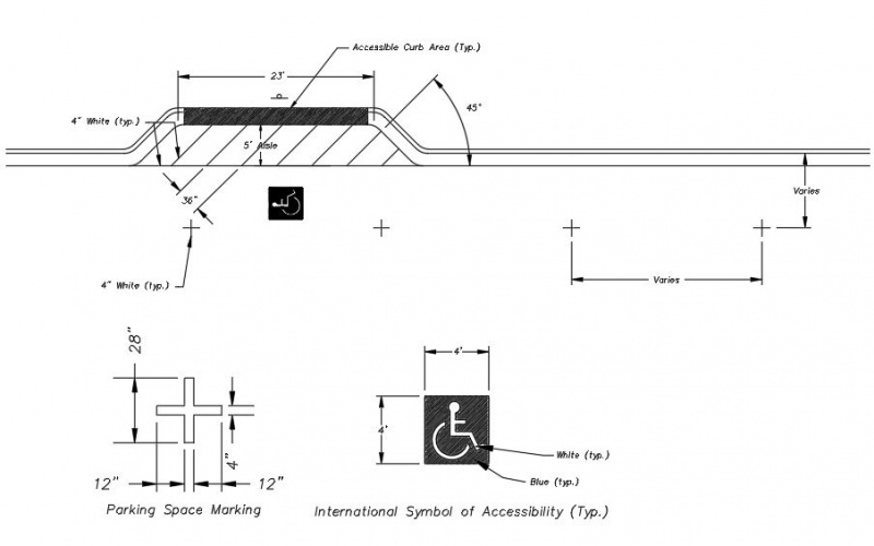
|
| Parallel Parking Space Markings |
International Symbol of Accessibility
The international symbol of accessibility shall be used in parking spaces that are for accessible parking spaces. It shall be 4’ square with a blue background and a white symbol. In perpendicular or angled parking spaces, the symbol shall be centered and located at the very beginning of of perpendicular or angle parking spaces as indicated in the standard details. In parallel parking spaces, the symbol shall be placed in the center (longitudinally and laterally) of a designated parallel parking space.
Electric Vehicle Pump Plug
The Electric Vehicle Pump Plug symbol for stalls associated with Electric Vehicle Charging Stations shall be used in parking spaces that are for EVs only. It shall be 4’ square with a black background and a white symbol. In perpendicular or angled parking spaces, the symbol shall be centered and located at the very beginning of of perpendicular or angle parking spaces as indicated in the standard details. In parallel parking spaces, the symbol shall be placed in the center (longitudinally and laterally) of a designated parallel parking space.
Speed Hump Markings
Speed hump markings are a series of white markings placed on a speed hump to identify its location. They will be “V” shaped markings inside a second “V” shape. They shall be 12” in width separated by 12” space. The “V” shaped markings are shown centered in each travel lane on the approach side of the speed hump with the “V” pointing in the direction of traffic flow in the lane. They tip of the largest “V” will be placed at the center of the speed hump. The width of the speed hump markings are 6’ as measured at the base of the triangle.
Advance speed hump markings should be used in advance of speed humps to identify vertical roadway deflections where the deflection is not expected. They shall be a series of eight 12” transverse lines that become longer and are spaced closer together as the vehicle approaches the speed hump. They shall begin 100’ in advance of the leading edge of the speed hump and arranged as indicated in the standard details.
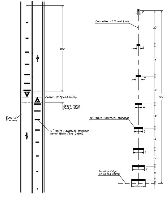
|
| Speed Hump Markings |

|
Top | Bicycle Markings |
Design Considerations
Before initiating the design of a pavement marking plan, the designer should contact the City staff to discuss the specific design criteria for the project and determine the scope. Decisions should be made in regard to the type of pavement and pavement markings that will be used in the design. The following is a brief summary of general design considerations.
Coordination with Pavement Joints
Offset lane lines a minimum of 6” from asphalt joints when possible. Maintain a minimum of 4” offset from all concrete pavement joints. This should be anticipated at the very beginning when determining the typical sections. Pavement marking lines should be shown and dimensioned on the typical sections.
Pavement Types and Approved Marking Materials
Pavement Marking Material and Surface Type Compatibility
The type of pavement surface will dictate the type of pavement marking material that should be specified. See the Pavement Marking Material Matrix below and the current standard details.
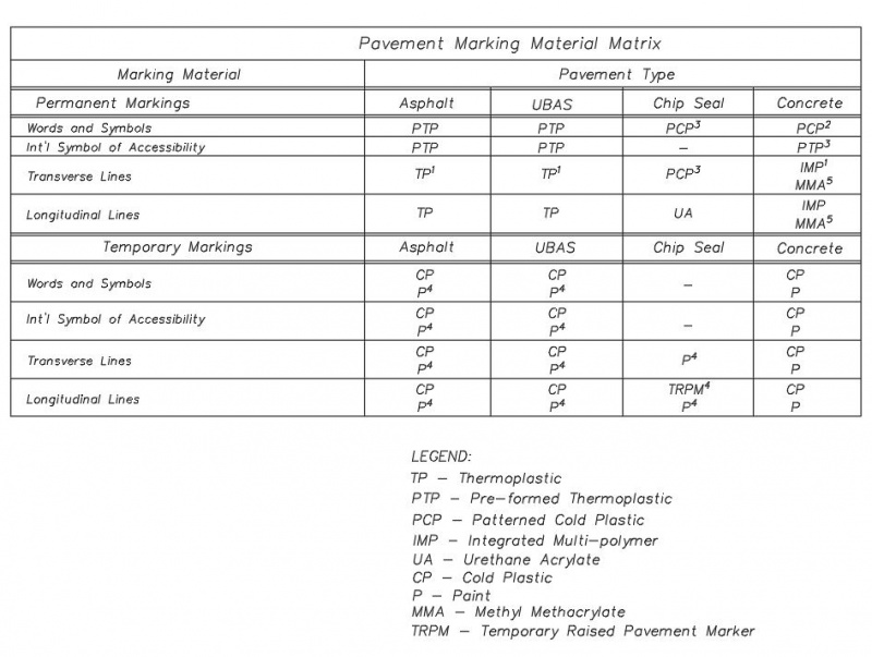
|
| Pavement Marking Material Matrix |
Preparation of Plans
The Plans shall be prepared in accordance with the following guidelines unless otherwise pre-approved by the Engineer
Scale
The preferred plan scale for pavement marking plans is 1” = 40’. Two lines of pavement marking plans may be on the same sheet above and below each other. A scale and north arrow shall be indicated on each sheet.
Topography
The only topography required for pavement marking plans are finished curb lines, including storm sewer inlets, median curb lines, drive entrances, sidewalks, bike trails, pavement limits and bridge limits. Also, include existing roadway limits at each end where the proposed pavement will tie in. If the mill and overlay of existing pavements is included, the existing curb and median lines should also be shown in those areas beyond the widening. If existing markings are being tied into at a match line, they should be surveyed and shown on the plans. If streetlighting is provided with the project, it is beneficial to show the symbol of the pole location so traffic control signs can be shown to be mounted on them, if applicable. A centerline shall be shown with stationing for the main roadway as well as the side streets to be able to positively locate the beginning and end of pavement marking lines. Street names shall be shown for major and minor streets.
New construction items should be subdued so the proposed pavement markings, lane width callouts, signing station and offsets, etc. stand out.
Plan Submittals
There should be a minimum of three plan submittals for every pavement marking project. Plans should be submitted at the Preliminary, Field Check and Final plan stage. An additional plan submittal may be required after the first final plan stage depending on how accurate the first submittal is.
Preliminary Plans
Enough work on the pavement marking plans should be completed such that the general lane layout is evident. The lines can be continuous instead of the final format just to help identify any glaring geometric issues that could be evident early on in the project design. Typical lane widths should be shown when it differs from the typical sections or at transition points.
Field Check Plans
Field check plans should show the location of all pavement markings, as they will be installed. The plans shall show callouts for the various types of lines and lane widths, etc. It is not required to show stationing for the beginning and end of pavement marking lines at this plan stage, nor is it required to have quantities calculated. However, standard details shall be included. Signing plans should also be incorporated into the pavement marking plans at this stage of design. All sign faces shall be shown with the MUTCD callout and size shall be shown oriented in the direction of travel.
Final Plans
All final pavement markings with stationing for the beginning and end of lines shall be included in the final plans, along with final signing plans with station and offsets for all sign locations. All sign faces shall be shown with the MUTCD callout and size shall be shown oriented in the direction of travel. All construction notes to clarify any construction details shall be shown. All Standard Details, including the completed Bill of Materials and the Pavement Marking Bid Item table shall be included at this stage. Depending on the number of comments made on the first submittal of final plans, a second set of final plans may be requested to verify that all comments have been addressed. The project manager will make that determination and convey his decision to the appropriate design staff.
Computation of Quantities
The computation of quantities is critical to providing accurate information to the contractors bidding the project. Errors in the computation of quantities results in project cost change orders and delays in the project. Care should be taken to check quantities against the plan sheet design to verify that all items are included and accurate. What follows are some general guidelines that should be used such that the computation of quantities is consistent for all designs.
Longitudinal and transverse lines
All longitudinal and transvers lines will be measured by the linear foot for the various materials used. The lines will be measured continuous from the beginning station to the end station. The pavement marking bill of materials includes multipliers for various line types that will be applied from the “start” to “end” length.
Symbols
All symbols, including turn arrows, thru arrows, “ONLY” markings, yield lines, merge arrows, bike lane symbol, sharrows, RR crossing symbols, etc. shall be measured per each, for the various materials used.
Temporary Raised Pavement Markers
Temporary Raised Pavement Markers (TRPMs) are used during chip seal pavement restoration operations. The existing thermoplastic, pre-formed thermoplastic, and patterned cold plastic pavement markings are ground off the roadway so the emulsion and layer of chips will bond to the roadway. TRPMs will be installed that meet the full requirements for substitution of the markings according to the MUTCD. The color of the TRPMs shall be the same color of the markings for which they substitute. The number and spacing of TRPMs is different for various line types. The discussion below discusses the value of N, which is equivalent to the length of one line segment plus one gap. Overland Park uses a 6’ line segment with an 18’ gap. Therefore, N = 6 + 18 = 24.
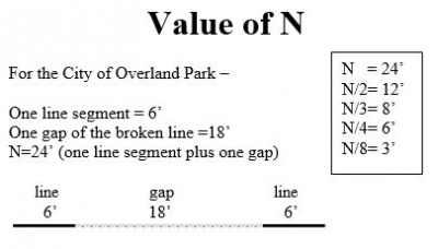
|
| TRPM Value of N |
Substitute for Broken Lane Lines
A group of at least three TRPMs shall be equally spaced at no greater than N/8 = (24/8) or 3’ spacing. Therefore, TRPMs will be located at each end of the broken lane line segment and one in the middle.
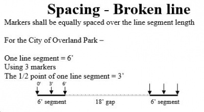
|
| TRPM Spacing for Broken Line |
Substitute for Solid Lane Lines
In the case of solid lines, the TRPMs shall be equally spaced at no greater than N/4 (24/4) or 6’ spacing. The value of N is the same as that referenced for the broken lines that might be adjacent to or might extend the solid lines.
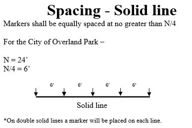
|
| TRPM Spacing for Solid Line |
Substitute for other Broken Lines
TRPMs may be used to substitute for other broken line segments that are shorter than 6’ by using at least one placed at the center of line segments of 2 to 3 feet in length.
Substitute for Double Solid Lane Lines
For solid double lines, TRPMs can be used as a substitute as long as two markers are placed side by side, with a horizontal separation that is equivalent to the spacing between the double lines. This would be equivalent to a 4” separation in Overland Park. The TRPMs shall be equally spaced at no greater than N/4 (24/4) or 6’ spacing.
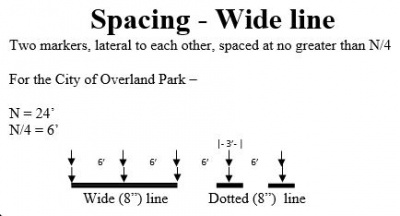
|
| TRPM Spacing for Wide or Double Line |

|
Top | Design Considerations |
